Wall thickness is the distance between the outer and inner surface of a part. In FDM the slicer builds it from perimeter lines, so the wall you draw in CAD only prints cleanly when it matches the line width the slicer will use. As a design rule, Formlabs gives 1 mm as the FDM minimum and notes that on a 0.4 mm nozzle a wall that is a multiple of 0.4 mm, such as 1.2 mm, will likely perform better than the bare minimum.
This guide splits the topic in two: the design minimum you model into the part, and the perimeter settings the slicer uses to build it. Strength comes mostly from perimeters rather than infill, according to Prusa’s slicer documentation. Numbers here come from Formlabs, Stratasys Direct, Prusa, the Cura Settings Guide and the OrcaSlicer wiki, linked at the end. Where a value is a starting point rather than a published figure, we say so.
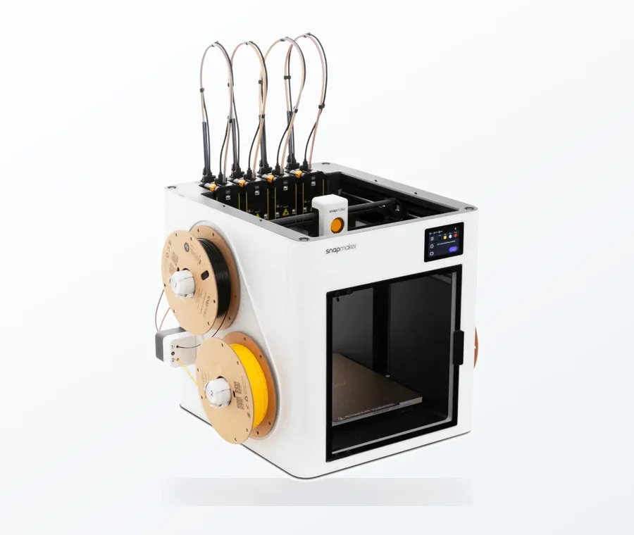
The consumer toolchanger 3D printer: the SnapSwap 4-toolhead system swaps heads in 5 seconds for true multi-color and multi-material printing, with smart calibration and auto filament loading.
- 4 toolheads · 5 s swap
- Up to 500 mm/s · 20,000 mm/s²
- 270 mm cube build volume
- Multi-color & multi-material
Wall thickness in 60 seconds
- Check the process minimum: 1 mm for FDM (Formlabs), 0.2 mm for SLA on Formlabs’s table, and more for real-world strength.
- Make walls a multiple of your line width: 0.8, 1.2, 1.6 mm on a 0.4 mm nozzle.
- Add perimeters before infill when you need strength. Two is the usual floor in Prusa profiles; load-bearing parts often use more.
- Let the slicer tell you its ideal thickness. PrusaSlicer shows a recommended value for your perimeter count and layer height.
- Avoid features thinner than one line width. The slicer may skip them.
- Print one section of the part and check the walls before committing to the full print.
Design minimum by process
A minimum is the thinnest wall a process can build reliably, not the thickness you want. It depends on the machine, the material and how the wall is supported.
| Source | Process | Minimum wall | Notes |
|---|---|---|---|
| Formlabs design table | FDM | 1 mm | With a 0.4 mm nozzle use multiples of 0.4 mm; 1.2 mm will likely perform better |
| Formlabs design table | SLA | 0.2 mm | Same value for supported and unsupported walls; varies by machine |
| Stratasys Direct (industrial FDM) | FDM, layer 0.127 mm | 0.508 mm | About 4 times the layer thickness |
| Stratasys Direct | FDM, layer 0.25 mm | 1.00 mm | Same 4x rule |
| Stratasys Direct | FDM, layer 0.33 mm | 1.32 mm | Same 4x rule |
| Stratasys Direct | FDM, layer 0.508 mm | 2.54 mm | Thick layers need thick walls |
A supported wall in Formlabs’s definition connects to other walls on two or more sides; an unsupported wall connects on fewer than two. Stratasys notes that thinner walls, down to about 0.2 mm, can be built case by case, so its minimums are conservative recommendations rather than hard limits. Those are industrial machines, though. On a desktop printer treat the minimums as a floor and work upward from the slicer rules below.
How a slicer turns wall thickness into perimeters
Your wall is built from perimeter lines laid side by side. Each slicer expresses that differently:
| Slicer | Setting you control | What it does |
|---|---|---|
| Cura | Wall Thickness or Wall Line Count | Wall Thickness adjusts the number of inner walls to reach the thickness; it must be a multiple of the wall line width and is rounded to the nearest multiple if it is not |
| PrusaSlicer | Perimeters | Sets the minimum number of outlines; Original Prusa profiles use a minimum of two |
| PrusaSlicer, OrcaSlicer | Wall generator: Arachne or Classic | Classic extrudes at a fixed line width; Arachne varies the width to follow the shape and handles thin features and transitions between wall counts better |
| OrcaSlicer | Wall Loops | Classic makes as many walls as Wall Loops allows at the defined Line Width |
Two details matter when you pick a thickness in CAD:
- Perimeters overlap. PrusaSlicer’s help explains that two 0.45 mm perimeters do not give 0.90 mm of wall. For a 0.2 mm layer height the suggested value is 0.86 mm, because the slicer overlaps neighbouring lines so they bond. Multiplying count by width gives a nominal figure, and the real number is a little lower.
- Non-multiples leave gaps or get adjusted. With a fixed line width (the Classic generator) a wall that is not a multiple of it ends in a gap or a thin fill line. Arachne widens or thins the lines to fit; Prusa says gap fill and small extrusions are significantly reduced. In PrusaSlicer 2.5.0 and later Arachne is the default, and “Detect thin walls” is disabled when it is on.
Nominal wall thickness by perimeter count
These are arithmetic on the line width, not tested values. Real walls come out slightly thinner because of overlap.
| Perimeters | 0.4 mm lines | 0.6 mm lines | Typical use (starting point) |
|---|---|---|---|
| 1 | 0.4 mm | 0.6 mm | Vase mode, decorative shells; fragile |
| 2 | 0.8 mm | 1.2 mm | Low-load and visual parts; the common profile floor |
| 3 | 1.2 mm | 1.8 mm | General functional parts |
| 4 | 1.6 mm | 2.4 mm | Parts that carry load or hold screws |
This agrees with the Formlabs example: 1.2 mm is 3 lines at 0.4 mm or 2 lines at 0.6 mm. The 0.6 mm column is simply 0.6 mm times the count.
Thin features the slicer may drop
A wall thinner than the minimum feature size can silently disappear from the preview. In PrusaSlicer and OrcaSlicer, Minimum feature size (set in millimetres or as a percentage of nozzle diameter) means features thinner than the value are not printed, and features above it are widened to the minimum perimeter width. Neither slicer’s documentation lists a default for this value, so look at your own settings before relying on it. PrusaSlicer’s help also says walls thinner than one extrusion width will likely still be ignored with “Detect thin walls”.
The practical rule for design: keep every wall, fin and text stroke at least one full line width thick, and preferably two. Check the layer preview in the slicer for gaps or missing walls before you print.
Walls vs infill: where strength comes from
PrusaSlicer’s help says model strength depends mostly on perimeter count, not infill, so more perimeters is the first way to make a part stronger. The Cura Settings Guide agrees: adjacent walls reinforce each other, and for larger prints adding walls can be more effective than raising infill, depending on the shape. The cost is real: more walls mean noticeably longer print times and more material.
Infill still matters where the part carries compression, or where a flat top needs something to bridge over; see infill pattern and density for that decision. Top and bottom layers follow layer height: Prusa’s example is 3 top layers at 0.3 mm layer height versus 9 at 0.1 mm for the same top thickness.
If a part still splits between layers, the problem is bonding, not thickness: see weak prints splitting between layers. For hollowing whole models, including resin, see hollowing 3D models.
Resin walls in brief
Resin printers can print much thinner walls than FDM, but thin resin walls are fragile and can warp or detach. Formlabs’s table gives 0.2 mm for SLA walls; its older Form 2 design specs, measured with Clear Resin at 100 microns, recommend 0.4 mm for both supported and unsupported walls and warn that thin walls can deform or weaken when washed in IPA. Both figures belong to Formlabs printers and resins, so for other machines use your resin maker’s guide. Brittle resin is a separate issue, covered in why resin prints are brittle.
Diagnosing wall problems
| Symptom | Likely cause | Fix |
|---|---|---|
| Thin gap or fill line inside a wall | Wall is not a multiple of the line width (Classic generator) | Change the CAD thickness to a multiple, or use Arachne |
| Thin fin or text missing from the print | Below the minimum feature size or under one line width | Thicken to at least one line width, check the preview |
| Wall looks like separate lines with visible gaps | Under-extrusion or a wrong flow ratio | Calibrate flow rate |
| Part snaps across the wall | Too few perimeters for the load | Add perimeters, then check layer bonding |
| Wall printed thicker than modeled | Over-extrusion, or the slicer widened a thin feature | Check flow and the minimum feature size settings |
Common wall thickness mistakes
- Modeling a 1 mm wall on a 0.6 mm nozzle and expecting two clean perimeters.
- Treating the process minimum as the recommended thickness.
- Raising infill to 80% while leaving two perimeters on a part that bends.
- Forgetting that a thread, screw boss or snap needs more wall than the plain shell; for threads, see printed threads.
- Making every wall thick. Thick sections cost time and material; only load paths need them.
Frequently asked questions
What is the minimum wall thickness for FDM?
Formlabs’s design table gives 1 mm for FDM, and notes that on a 0.4 mm nozzle a multiple of 0.4 mm such as 1.2 mm will likely perform better. Stratasys Direct recommends about four times the layer thickness on its industrial machines. Treat both as starting points and test on your own printer.
How many perimeters should I use for a strong part?
Prusa’s profiles use at least two, and its help says strength depends mostly on perimeter count rather than infill. For parts under load, three or four walls are a common starting point; raise the count and check where the part actually fails.
Why did my thin wall not print?
The slicer drops features thinner than its minimum feature size, and walls thinner than one extrusion width may be ignored. Thicken the wall to at least one line width, or two, and look at the layer preview before printing.
Do I need the wall to be an exact multiple of the nozzle diameter?
With the Classic wall generator a multiple of the line width gives the cleanest result; Cura rounds Wall Thickness to the nearest multiple. With Arachne the slicer varies the line width, so odd thicknesses fill better, but multiples are still the safer design choice.