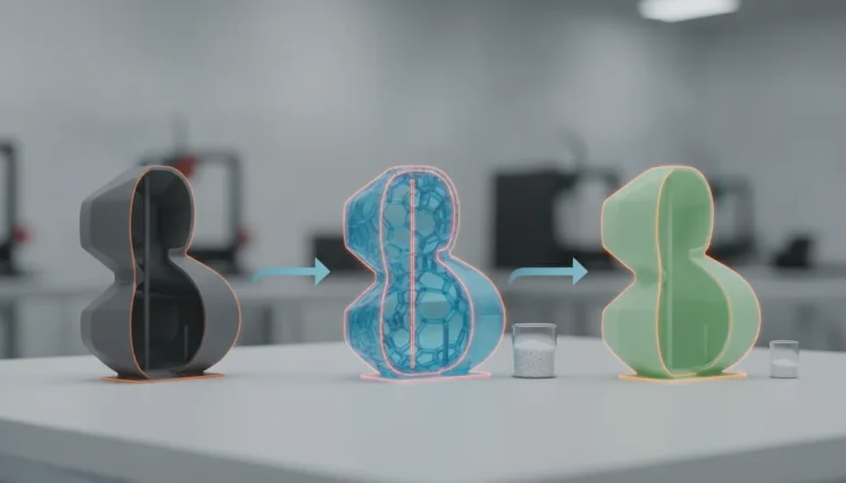
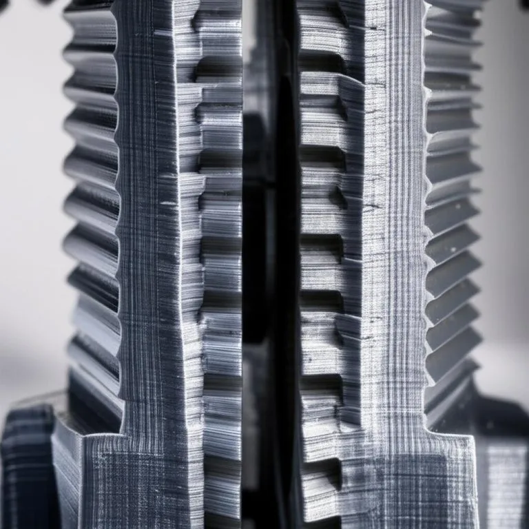
A bridge in 3D printing is a horizontal run of plastic printed between two supports with nothing underneath, such as the roof of a slot or the top of a window opening. On the design side the rule is simple: keep unsupported spans short, and where you cannot, split them, support them from the model or hide the bad underside. Protolabs Network and Xometry both put the limit for a bridge without sagging or support marks at 5 mm; Prusa says only that short horizontal bridges can be printed without supports and gives no limit.
Longer spans do print, but the underside tends to sag and get rougher as the span grows and the sources we read give no universal maximum beyond that 5 mm figure. This guide covers the model-side fixes: span length, ribs and arches, flat-roof holes, counterbores and sequential bridges, then hands over to the slicer. Numbers come from the sources at the end (checked as of 2026); dimensions in the test model are examples to adapt.
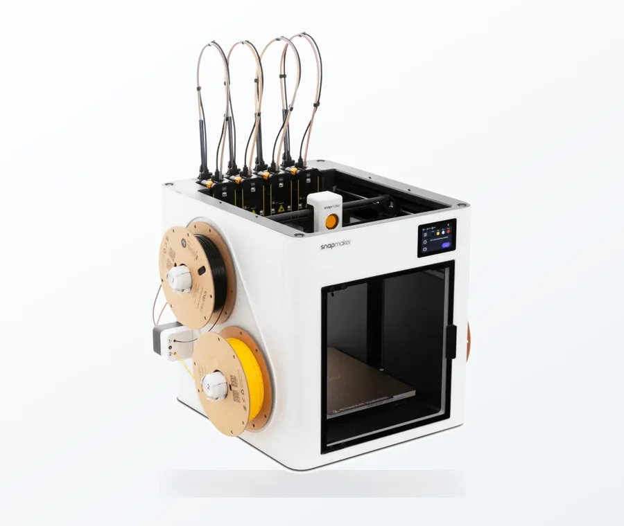
The consumer toolchanger 3D printer: the SnapSwap 4-toolhead system swaps heads in 5 seconds for true multi-color and multi-material printing, with smart calibration and auto filament loading.
- 4 toolheads · 5 s swap
- Up to 500 mm/s · 20,000 mm/s²
- 270 mm cube build volume
- Multi-color & multi-material
Bridge design checklist
- Measure every unsupported horizontal span in the model, in the direction of the shortest gap.
- Spans under about 5 mm: leave them. Longer spans on a visible or functional surface: shorten or support them.
- Add a rib, wall or post under the middle of a long span, or turn a flat ceiling into an arch or a pitched roof.
- Give flat-roof holes extra clearance for droop, or switch to a teardrop.
- Over an upside-down counterbore, model a one-layer sacrificial bridge or a stepped bridge.
- Print a small span test on your own printer and design to that result.
How long can a bridge be?
| Source | What it says about span | Note |
|---|---|---|
| Protolabs Network | Sagging or support marks are present unless the bridge is shorter than 5 mm | Design-for-FDM guide; the same article offers splitting the part or post-processing for longer bridges |
| Xometry | Bridges longer than 5 mm may need extra supports or design changes | FDM design tips |
| Prusa Knowledge Base | Short horizontal bridges can be printed without supports | No span limit given |
| Your printer | Whatever your span test shows for your material, cooling and speed | Use as the real design limit |
Treat 5 mm as a quality threshold, not as a physical limit. It describes when the underside stays flat and clean. If the underside is hidden or does not need to be flat, a longer bridge can be fine. If it must be flat, the numbers above are the conservative starting point.
Make your own span test
A bridge test is a short model that has several gaps of increasing width between two posts. As an example, model posts 10 mm wide and 10 mm tall, separated by gaps of 5, 10, 15, 20 and 30 mm, with a bridge on top that is a few layers thick. Print it in the material and layer height you will use, then measure or inspect the underside of each span. Pick the longest span whose sag you can live with and make that your design limit for this printer and filament. These gap sizes are an example set, not a recommended standard.
Ways to shorten or hide a bridge in the model
- **Add a rib or wall.** An internal rib cuts one long span into two short ones. Prusa’s slicer documentation uses the same idea in the slicer: a support enforcer placed in the middle of a bridge splits it into smaller bridges.
- **Use an arch or a pitched roof.** Replace a flat ceiling over a cavity with a triangular or arched cross-section so every surface is within the 45° overhang rule (see support-free design).
- **Chamfer the ends of the span.** A 45° chamfer where the span meets each wall turns part of the gap into a printable slope, so the flat bridged section is shorter.
- **Orient the part differently.** Rotating a part 90° can turn a horizontal hole or slot into a vertical one with no bridge at all, as Protolabs Network recommends for holes. Vertical holes tend to print undersized, so for a critical diameter, print smaller and drill. See orientation for strength for the trade-off.
- **Split the part.** Prusa says splitting a model into parts can reduce the support needed, and the parts can be glued together afterwards.
- **Hide the underside.** If the bridge is inside an enclosure or under a label recess, let it sag.
Flat-roof holes and counterbores
A round hole through a vertical wall has a bridge at its very top. The Rahix design guide uses two shapes: a teardrop with a 90-degree tip for small holes (its example is a 4 mm hole) and a flat roof for larger ones (a 10 mm example). A flat roof needs a little extra clearance below it because bridges droop slightly; the guide places the roof 0.4 mm above the theoretical circle in its 10 mm example. Treat 0.4 mm as an example to adapt.
A counterbore printed wide-end down has a ring-shaped overhang around the smaller hole, and it cannot bridge normally because the hole is in the way. The same guide gives two fixes:
- **Sacrificial bridge:** model a bridge one layer thick across the whole counterbore. The small hole prints on top of it, and you cut or drill the thin layer out afterwards. Cutting can leave loose strands.
- **Stepped bridges:** in the first layer, bridge only two strips either side of the small hole; in the next layer, bridge across them at 90° so that a square the size of the hole remains; then print the circle from the layer after. Nothing needs cutting, but the guide notes it gets harder as the diameter grows, and gives 0.2 mm as a typical layer cut.
OrcaSlicer can do the same at slice time. Its Bridge counterbore hole setting (counterbore_hole_bridging) has none, partiallybridge and sacrificiallayer options.
Bridges on top of bridges
The Rahix guide describes sequential bridging: one bridge can support the next, allowing complex geometry without support structures. For large bridges it recommends building the lower bridge up for a few layers before starting the next, which gives it more strength and time to cool. That is a design rule worth keeping in mind for lattices and ceilings.
Inside a normal part, the top skin of a hollow with sparse infill is also a bridge. OrcaSlicer’s bridging page lists settings for it: thick internal bridges (it recommends enabling them for internal bridges) and an extra bridge layer option meant to reduce pillowing on the top surface. Those settings belong to the slicer, so the sagging bridges and overhangs guide covers speed, flow and fan, and part cooling covers the fan hardware.
Telling the slicer what you designed
- **PrusaSlicer:** “Don’t support bridges” prevents support from being generated under bridged areas. Support enforcers and blockers let you place support only where you want it.
- **Top contact Z distance:** Prusa’s article says setting it to 0 prevents PrusaSlicer from using bridge flow and speed for the first object layer, so keep a nonzero gap when you want the roof above a support to print as a bridge.
- **OrcaSlicer:** the bridging page lists the bridge flow ratio, bridge density, thick bridges and extra bridge layers as settings.
- **Targeted supports:** if one span still fails, add a small support under it with manual support placement instead of enabling supports for the whole model.
Common bridge design mistakes
- **Designing to your printer’s best result.** A span that works on your tuned machine may droop on someone else’s. For shared models, stay near the conservative 5 mm figure.
- **No clearance under a flat roof.** The hole comes out too tight once the bridge sags.
- **A support Z gap of 0.** Prusa notes that a top contact Z distance of 0 stops PrusaSlicer from using bridge flow and speed on the first object layer.
- **Round holes in horizontal walls left as circles.** The top of the circle is a small bridge; use a teardrop or flat roof.
- **Treating a rough underside as a failed print.** If the surface is hidden and the part functions, it may be good enough.
Frequently asked questions
How long can a bridge be in 3D printing without supports?
Protolabs Network and Xometry both say that bridges longer than 5 mm may sag or leave marks, and that shorter ones usually stay clean. Longer spans can print, but the underside gets rougher as the span grows. Print a span test to find your own printer’s limit.
How do I print a horizontal hole without supports?
Give it a teardrop shape with a 90-degree tip pointing up, or cut the top flat and leave extra clearance for droop. The Rahix design guide uses a 4 mm teardrop and a 10 mm flat-roof example with the roof 0.4 mm above the circle. If the design allows, rotate the part so the hole is vertical.
How do I make a bridge shorter in the model?
Add a rib or wall to cut a long span into shorter ones, or replace a flat ceiling with an arch or a pitched roof. Chamfering the corners under the span and splitting the part into pieces also help.
Is a sagging bridge a design problem or a slicer problem?
It can be both. If the span is much longer than 5 mm, shorten it in the model. If it is short and still sags, look at cooling, speed and bridge flow in the slicer.