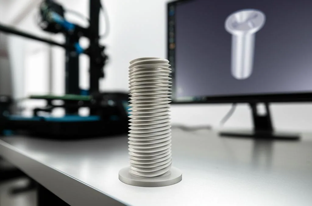
A 3D printed thread is a helical profile that you model as real geometry in the part, because the slicer prints only what is in the STL file. It works reliably when the thread is large and coarse (M6 or bigger is the conservative starting point), when you leave a small clearance between the two halves, and when you print it standing upright. For small screws, or anything you will screw and unscrew many times, a heat-set insert or a metal screw is the better answer.
Clearances are printer-dependent, so the numbers below are starting points for a test print, not guarantees. They come from a printer maker’s design article, an industrial FDM design guide, an insert supplier and the help pages of two CAD programs; all are linked at the end.
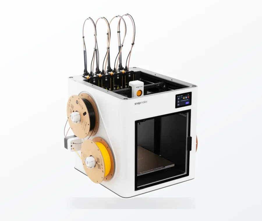
The consumer toolchanger 3D printer: the SnapSwap 4-toolhead system swaps heads in 5 seconds for true multi-color and multi-material printing, with smart calibration and auto filament loading.
- 4 toolheads · 5 s swap
- Up to 500 mm/s · 20,000 mm/s²
- 270 mm cube build volume
- Multi-color & multi-material
Printed thread in 60 seconds
- Choose the method: modeled thread for large, low-torque parts; heat-set insert or metal screw for small or often-assembled joints.
- Model a real thread, not a cosmetic one. Check the exported STL, not the CAD view.
- Use a coarse profile with rounded roots and crests, and a 45° lead-in chamfer.
- Add clearance: start around 0.10–0.20 mm per side (0.20–0.40 mm on the diameter) and adjust after a test print.
- Print the thread axis vertical, with 3–5 walls and a layer height of 0.12–0.16 mm on a 0.4 mm nozzle.
- Print a short thread coupon first, then the real part.
Printed thread, insert or tap: which to use
A printed thread costs nothing extra and needs no hardware, but plastic threads wear faster than a metal insert and creep under sustained load. A printer maker’s thread guide limits printed threads to low-stress parts such as container lids and jigs, and advises brass heat-set inserts for high strength or repeated assembly. An industrial FDM guide goes further: lock nuts, embedded nuts and metal inserts are all stronger fastening options than adding threads directly to the plastic.
| Method | Good for | Weak point | Notes |
|---|---|---|---|
| Modeled thread printed with the part | Lids, caps, knobs, large adjusters, jigs | Wears faster than metal, weak under torque, size limits | Needs clearance tuning for your printer |
| Heat-set brass insert | Screws that go in and out, higher loads | Needs a hole sized for the insert and enough wall around it | Installed with a soldering iron |
| Self-tapping metal screw into a plain hole | One-off assembly, light loads | Loosens if reassembled often | Use the screw maker’s pilot hole and validate with a coupon |
| Tap or die after printing | Cleaning up a printed thread, larger sizes | Needs wall thickness, easy to strip plastic | An industrial FDM guide lists tapping as a post-process option |
| Captive nut pocket | Bolt and nut joints | Needs a modeled pocket | Embedded nuts count as a stronger option than printed threads |
For inserts, use the insert maker’s drawing. As one example, Weerg’s guide for FDM and MJF lists a host hole of 4.0 mm for an M3 insert (5.7 mm long) and 5.6 mm for an M4 (8.1 mm long), with a minimum distance to the wall of 1.6 mm and 2.1 mm, and says blind holes should be at least 1 mm deeper than the insert. The industrial guide suggests at least 0.080 in (about 2 mm) of wall around the outside diameter of the insert. Sovol quotes a soldering iron temperature of roughly 250–300 °C for brass inserts in M2 to M5; the melted plastic flows around the knurled surface to hold the insert. Insert makers publish their own temperatures and hole sizes, so follow yours. Our guide to ABS post-processing covers heat-set inserts in more detail.
Minimum size and thread profile
Sources disagree on how small a printed thread can go. The Stratasys Direct FDM guide advises avoiding threaded holes smaller than 0.15 in (about 3.8 mm) and posts smaller than 0.08 in (about 2 mm), and that is on industrial machines with soluble support. A printer maker’s guide for desktop FDM calls M6 and larger a conservative starting point with a 0.4 mm nozzle, and says smaller threads can work on a well-tuned printer if you test the clearance. If you want an M3 or M4 screw to hold a part together, an insert or a tapped metal screw is more dependable than a printed thread.
For the profile:
- Avoid sharp edges. Sharp roots act as stress concentrators in plastic. Stratasys found that an ACME-style thread with rounded roots and crests works well in FDM.
- Keep the pitch coarse. The Sovol guide gives M6 and up as typically 1.0 mm pitch or more, and suggests custom coarse threads of 2–4 mm pitch with rounded roots.
- Match layer height to pitch. The same guide suggests keeping layer height at roughly one sixth to one eighth of the pitch. For a 1.2 mm pitch with 0.15 mm layers that is 8 layers per turn.
- Add a root fillet of 0.2–0.5 mm, according to the same guide.
- Add an entry chamfer. Sovol suggests 0.8–1.5 mm at 45° on both the screw tip and the nut opening so the parts start without cross-threading.
Clearance: how much room to leave
Extruded plastic is slightly wider than the nozzle and holes tend to print undersized, so two threads modeled to the same nominal size will usually jam. The usual fix is to model both to nominal size and then open up the fit.
| Source | Value | What it applies to |
|---|---|---|
| Sovol thread guide | 0.10–0.20 mm radial per side (0.20–0.40 mm on the diameter), as a test starting point | Printed threads on a desktop FDM printer |
| Sovol thread guide | Offset an external thread by about -0.10 to -0.20 mm, with -0.15 mm as a baseline | External thread, modeled with a face offset |
| Stratasys Direct guide | Clearance tied to layer thickness (the example is 0.010 in layers with 0.010 in clearance) | Industrial FDM machines, so a different scale from desktop printers |
The spread shows why there is no universal number. Your nozzle, layer height, flow calibration and material all move the result. Get the flow right first (see flow rate calibration), because over-extrusion closes the gap more than any CAD value does.
Print a thread coupon first
The Sovol guide describes a short test piece, and it saves hours on larger parts:
- Model two or three full turns of the thread with the same wall thickness as the final part.
- Print it with the final layer height, wall count and material.
- Screw the halves together by hand.
- If the fit binds, increase the clearance in small steps (0.05 mm is a sensible step to try). If it is loose, reduce the clearance or increase the engagement length.
- Write the working value down for that printer and material.
Orientation, walls and material
Orientation. Print the thread axis along Z. Sovol notes that a vertical thread is a good starting point for accurate circular threads. A thread printed lying down comes out stepped or oval and needs supports inside the thread. Horizontal does improve tensile strength along the shank, so use it only when the load demands it and accept the supports. More on the trade-off in our print orientation guide.
Walls and engagement. Perimeter count matters more than infill for thread strength. The Sovol guide recommends 3–5 perimeters, or a wall of 1.6–2.0 mm, and an engagement depth of 2.0–2.5 times the screw diameter for plastic. See wall thickness for how those walls map to slicer settings.
Layer height. 0.12–0.16 mm on a 0.4 mm nozzle is the range given by that guide. Finer layers cost print time but give a smoother thread profile.
Material. PLA is stiff but brittle under torsion and creeps under sustained load, so PETG or ASA are the usual picks for a screw or cap that gets turned often. Compare options in our guide to strong filaments. Do not use printed threads for high-load, high-temperature, pressure-containing or safety-critical joints without load testing the actual part.
Getting real threads out of your CAD program
The thread you see on screen may not exist in the file you export. Features and menu names change between versions, so these notes reflect the vendors’ help pages as of 2026.
- Fusion: go to Create > Thread in the Design workspace’s Solid tab and select the hole or cylinder face. The Thread dialog has a Modeled checkbox: cosmetic threads only show the appearance and are the default, while modeled threads are cut into the geometry. Autodesk’s help adds that modeling threads is useful for 3D-printed parts. Untick Full Length if you want to set an offset and length. Thread type, size, designation, class and direction are set in the same dialog.
- Onshape: the Hole feature has a Tapped option with tap types such as straight tap, but Onshape’s help describes the resulting threads as cosmetic, a visual representation that does not affect geometry. That page does not show a one-click modeled thread, so check Onshape’s current documentation or model the helix yourself if you need real geometry.
- Any program: if the thread is a texture, a decal or a “cosmetic” feature, it will be missing from the STL. Open the exported STL and zoom in before you slice.
Common thread mistakes
- Printing a cosmetic thread and wondering why the screw spins freely.
- Using the same nominal size for both halves, with no clearance.
- Printing the thread on its side to save supports, which squashes the profile.
- Choosing a fine pitch (under about 1 mm) on a 0.4 mm nozzle, where neighbouring turns can merge.
- Expecting printed M3 threads to survive repeated assembly. Use an insert.
- Skipping the coupon and wasting a long print on a wrong clearance.
If a thread comes out weak or splits along the layers, the cause is often print quality rather than the CAD. To avoid supports inside a thread or around it, our support-free design guide shows how to design around overhangs.
Frequently asked questions
What clearance should I use for a 3D printed thread?
Start around 0.10–0.20 mm per side (0.20–0.40 mm total on the diameter) and print a short test coupon to adjust. The right value depends on your printer, nozzle, layer height and flow calibration, so treat these as starting points rather than fixed rules.
What is the smallest thread I can 3D print?
Sources disagree. An industrial FDM guide avoids threaded holes below about 3.8 mm, while a printer maker calls M6 a conservative minimum on a 0.4 mm nozzle. For M3 to M5 screws, a heat-set insert or a metal screw in a thick wall is usually the safer route.
Should I print threads vertically or horizontally?
Vertical (thread axis along Z) gives the most accurate, round threads and needs no supports inside. Horizontal can improve tensile strength along the shank but gives stepped or oval threads and needs support, so use it only when the load direction requires it.
Why does my modeled thread disappear in the slicer?
It was probably a cosmetic thread. In Fusion, tick Modeled in the Thread dialog; in other programs, check that the thread is real geometry in the exported STL.