Print orientation is the way you rotate a model on the build plate before slicing, and on an FDM printer it decides where the layer boundaries fall. Those boundaries are the weak direction: Prusa’s published figures put the tensile strength of Prusament PLA across the layers (Z) at about a third of its strength along them (XY). So orient a load-bearing part so the force runs along the layers, never so that it pulls layers apart or peels them off each other.
In practice that usually means laying hooks, brackets and clips on their side so their curves and corners are drawn within each layer. This guide shows how to work out the load direction, how to orient common parts, what to do when the strongest orientation needs too much support, and why resin prints follow different rules. Sources are linked at the end.
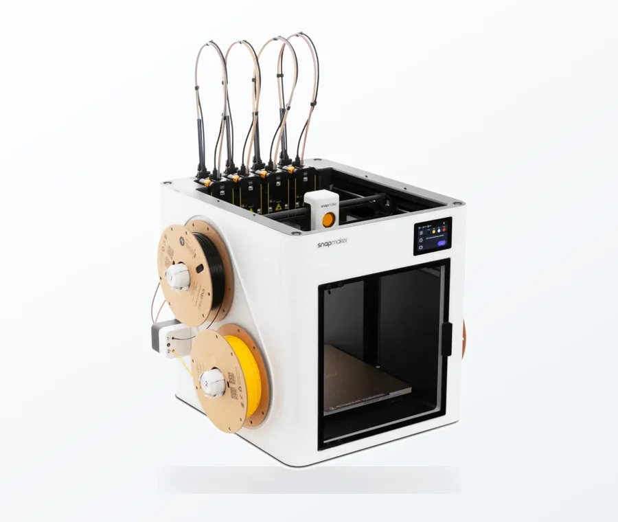
The consumer toolchanger 3D printer: the SnapSwap 4-toolhead system swaps heads in 5 seconds for true multi-color and multi-material printing, with smart calibration and auto filament loading.
- 4 toolheads · 5 s swap
- Up to 500 mm/s · 20,000 mm/s²
- 270 mm cube build volume
- Multi-color & multi-material
Orientation for strength in 60 seconds
- Work out where the part will break: find the point of highest stress, usually an inside corner, a thin neck or the root of a hook or clip.
- Work out the load there: pulling, bending, twisting or crushing.
- Rotate the model so that stressed area lies flat in one layer, with the force running along the layers.
- Check supports, overhangs and bed contact in the slicer preview. If the strong orientation is unprintable, split the model or add walls.
- Do not trust auto-orient for strength: it optimises for support, surface or height, not for load.
Why FDM parts are weakest between layers
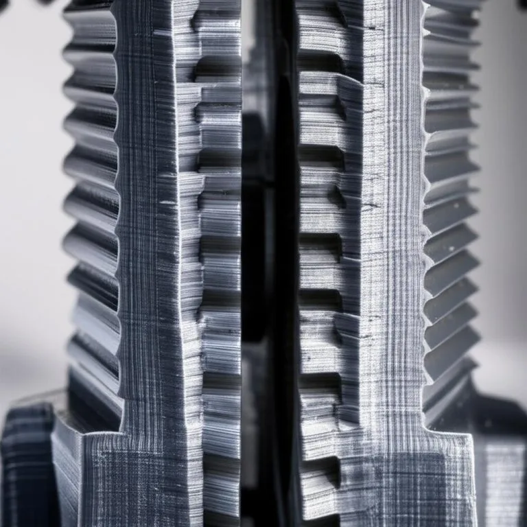
Within a layer, each extruded line is a continuous strand of plastic, and neighbouring lines are pressed together while hot. Between layers, each new layer is laid onto one that has already started to cool, so the bond is weaker and the contact area smaller. Formlabs sums it up: in FDM the layers are not bonded as strongly as the lines themselves, and there are voids between them. The result is anisotropy: the same part is strong in one direction and much weaker in another.
Prusa quantifies this with a tensile strength anisotropy coefficient, r = σz / σxy: the tensile yield strength across the layers divided by the strength along them. At 1.0, a material would be equally strong in every direction.
| Material (Prusament) | Anisotropy coefficient r | What it means |
|---|---|---|
| PLA | 0.33 | Across the layers, about a third of the strength along them |
| PC Blend | 0.33 | Same ratio as PLA |
| PETG | 0.38 | Slightly better, still well under half |
| PLA High Speed | 0.60 | Prusa’s figure for its high-speed PLA; better layer bonding, still anisotropic |
These are Prusa’s figures for its own filaments; the article does not state the print settings behind them, and other brands, temperatures and cooling will give different numbers. A study cited by Formlabs found FDM strength across the layers at around 55% of strength along them. The exact ratio varies, but every source points the same way: the layer boundary is the weak link.
How to orient common parts
The question for every part is the same: if you imagine it breaking, would the crack run between two layers? If yes, rotate it until the crack would have to cut through the extruded lines instead.
| Part | Load | Orientation | Why |
|---|---|---|---|
| Wall hook | Bending at the curve | On its side, so the whole J shape is drawn in each layer | Printed upright, the curve is stacked from layers and snaps between them |
| L-bracket or shelf bracket | Bending at the inside corner | On its side, both legs flat on the bed | The corner is continuous in every layer instead of being a layer boundary |
| Snap-fit clip, latch | Repeated bending of the arm | Flex direction within the layers | An arm that bends across layer lines cracks after a few cycles |
| Spur gear | Bending at the tooth root | Flat on its face | Each tooth is drawn whole in every layer; stood on edge, teeth break along layer lines |
| Pin, peg, standoff | Bending or shear | Lying horizontal | A vertical pin snaps at a layer line; accept the flat side or add a small flat to the design |
| Threaded bolt | Tension along the axis | Horizontal for strength, vertical for thread shape | A vertical bolt pulls layers apart; a horizontal one has the best axial strength but rougher threads underneath |
| Spacer, foot, block under pressure | Compression | Whatever prints best | Compression pushes layers together, so orientation matters less |
For parts with loads from several directions, find the one that will actually break it. A bracket that carries a shelf fails at the corner; a hook fails at the curve. Optimise for that failure and let the rest follow.
When the strong orientation needs too much support
The strongest orientation is often not the easiest to print. Laying a part on its side can create large overhangs, a small first layer or supports against a visible face. Before giving up strength, try these in order:
- Accept some supports. Support marks on a hidden face cost less than a part that breaks. Tree supports leave fewer contact points, and good support removal keeps the surface tidy.
- Split the model. Prusa suggests changing the orientation or splitting the model into several parts to reduce overhangs. Each piece can then be printed in its own strong orientation and glued or bolted together, as long as the joint is not the highest-stress point.
- Change the design. Add a small flat to a round pin so it lies stable, fillet inside corners, or thicken the section that crosses layer lines.
- Compensate with settings if none of that works (next section).
In the slicer, the overhang threshold is set as the most horizontal slope you can print without support, measured from the horizontal plane (90° is vertical). Check the preview after each rotation: the support volume and the first-layer footprint change a lot between orientations of the same part.
Settings that help when you can’t reorient
- More perimeters. Prusa’s documentation says a model’s strength is mostly defined by the number of perimeters, not the infill. Original Prusa profiles use at least two; a functional part in a weak orientation benefits from more.
- Better layer bonding. Printing at the hotter end of the filament’s range and avoiding excessive cooling help layers fuse. The guide to weak layer adhesion covers the settings in detail.
- Layer height within limits. Prusa keeps layer height below 80% of the nozzle diameter, about 0.32 mm on a 0.4 mm nozzle.
- Infill that suits the load. Infill helps less than walls, but a pattern with strength in every direction is a better match for mixed loads; see the guide to infill pattern and density.
- A filament with better layer bonding. Prusa’s own figures show large differences between materials (the table above), so switching material can matter as much as tuning.
Resin prints: orientation for success, not strength
Resin (SLA, MSLA, DLP) parts behave differently. Formlabs tested tensile bars printed at 15° steps from 0 to 90° on a Form 2 and found the maximum stress and stiffness stayed roughly constant across build angles, because the layers bond chemically rather than just sticking together. Those specimens were washed and post-cured first, and the test covers Formlabs’ own resin, so treat it as the general principle rather than a guarantee for every resin.
On a resin printer, orientation is mostly about getting a successful print and a clean surface. Prusa’s SLA guidance is to place parts at about 45°: large flat surfaces need a lot of force to separate from the tank after each layer, while a tilted part spreads its supports more evenly. Rotate to reduce islands, the spots where a layer would start in mid-air, and keep support marks off visible faces.
Common orientation mistakes
- Printing the model as it was drawn. CAD models are usually drawn upright, which for hooks, brackets and clips is the weakest way to print them.
- Using auto-orient on a functional part. PrusaSlicer’s optimize orientation tool, for example, offers best surface quality, reduced overhang slopes or lowest Z height. None of those options knows where the load goes.
- Adding infill to fix a layer-line break. If the part broke cleanly between layers, more infill will not stop it. Change the orientation or add walls.
- Ignoring warping in the new orientation. A part stood on a small footprint or a long thin edge can lift off the bed. For warp-prone materials, see ABS warping before reorienting large parts.
- Applying FDM rules to resin. Resin parts do not need to be laid flat for strength; tilt them for the print.
Frequently asked questions
Which direction is strongest on a 3D print?
On an FDM print, the strongest direction is along the layers, in the X-Y plane of the bed. The weakest is across the layers, along Z. Prusa’s figures for Prusament PLA put strength across the layers at about a third of the strength along them.
Should I print a hook upright or on its side?
On its side, so the whole curve of the hook is drawn in every layer. Printed upright, the curve is built from stacked layers and the load bends them apart at the most stressed point. The side orientation may need a little support, which is a fair trade for a hook that holds.
Does print orientation matter for resin prints?
For strength much less than on FDM: Formlabs’ tests on washed and post-cured parts showed nearly the same strength at every build angle. Orientation still matters for print success, support placement and surface finish, which is why resin parts are usually tilted, often around 45°.
Can I rely on my slicer’s auto-orientation?
Not for strength. Auto-orientation tools optimise for things like surface quality, overhangs or height, and they do not know how the part will be loaded. Use them as a starting point, then rotate so the highest-stress area lies within the layers.