Designing for support-free printing means shaping a part so that every surface either rests partly on the layer below or spans a short gap as a bridge, so the slicer never has to add supports. Four rules cover most parts: keep overhangs within about 45° from vertical, keep unsupported bridges short (Protolabs Network puts the limit for a clean, mark-free bridge at 5 mm), use chamfers rather than fillets on downward-facing edges, and give horizontal holes a teardrop or flat-roof shape.
This guide covers the design side: the rules above, sacrificial layers for counterbores, splitting parts and choosing an orientation. The values come from Prusa, Protolabs Network, Xometry and two independent design guides linked at the end; where a value is a starting point, we say so. Once the model is right, the slicer does the rest: fan, speed and bridge flow are in the companion guide on sagging bridges and overhangs.
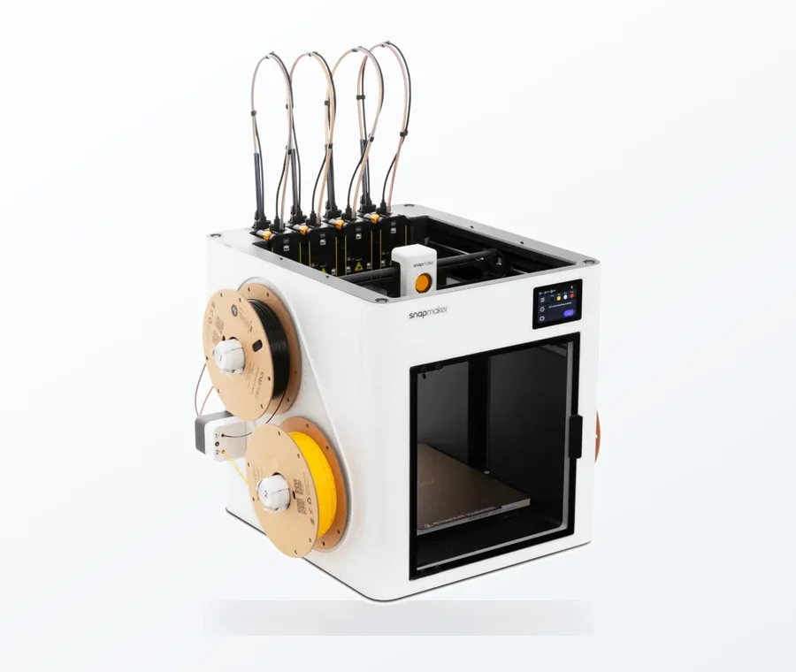
The consumer toolchanger 3D printer: the SnapSwap 4-toolhead system swaps heads in 5 seconds for true multi-color and multi-material printing, with smart calibration and auto filament loading.
- 4 toolheads · 5 s swap
- Up to 500 mm/s · 20,000 mm/s²
- 270 mm cube build volume
- Multi-color & multi-material
Support-free design checklist
- Pick the print orientation first: the largest flat face on the bed, the fewest downward-facing surfaces.
- Check every downward-facing surface: steeper than 45° from vertical needs a redesign or support.
- Replace fillets on horizontal, downward-facing edges with 45° chamfers.
- Turn horizontal round holes into teardrops (point up) or give them a flat roof.
- Keep bridges short; break long spans with a rib or wall.
- Add a one-layer sacrificial bridge over upside-down counterbores.
- If no orientation works for the whole part, split it and join the pieces.
The 45° rule: how steep an overhang can be
An overhang is any surface where a layer is wider than the one below it. Measured from vertical, 0° is a straight wall and 90° is a flat ceiling. Protolabs Network’s rule is that, depending on the material, an overhang can usually be printed up to 45° without losing quality; at 45°, the new layer is supported by 50% of the previous one. Beyond that the layer edge bulges down and curls, and you need support.
Treat 45° as the value to design to, not a hard limit. Prusa puts the clean range at 45–60° depending on nozzle diameter and settings, and says its printers with the Nextruder and 360° cooling handle overhangs up to 75° without supports. A design that stays at 45° prints on almost any machine; a design that needs 70° only prints well on a well-cooled, well-tuned one.
Watch the angle convention. Most design guides measure from vertical. Bambu Lab’s documentation measures between the surface and the bed, so the same slope has a different number in each system. Only 45° reads the same both ways, which is one reason the rule is quoted so often.
| Feature | Design value to start from | Source |
|---|---|---|
| Overhang angle | Up to 45° from vertical without support | Protolabs Network, Xometry |
| Overhang on a well-cooled printer | 45–60°; up to 75° on Prusa’s Nextruder printers | Prusa |
| Bridge length | Under 5 mm for a surface without sag or support marks; longer may need support or a design change | Protolabs Network, Xometry |
| Edges touching the bed | 45° chamfer (or radius) where dimensions matter | Protolabs Network |
| Small horizontal hole | Teardrop with a 90° tip, pointing up | Rahix design guide (blog) |
| Large horizontal hole | Flat roof, raised slightly for bridge droop (0.4 mm in a 10 mm example) | Rahix design guide (blog) |
The bridge figure is about surface quality, not whether a bridge can be printed at all. Printers routinely bridge longer gaps; they just leave a slightly sagging, rougher underside. If the underside of a lid or a slot roof does not need to be flat, a longer bridge is fine.
Chamfers vs fillets: which edge gets which
The same round edge prints very differently depending on which way it faces:
- Horizontal edges facing down: chamfer. A fillet here starts with a nearly flat, very steep overhang at its lowest point. Prusa’s advice is to use a chamfer instead if surface finish matters. A 45° chamfer keeps a constant angle, so the layer steps look even.
- Horizontal edges facing up: a fillet prints without overhang, but its changing curvature makes the layer steps very visible. A chamfer still looks cleaner.
- Vertical edges: fillet. On edges that run up the Z axis, a fillet lets the nozzle go round the corner without slowing down, while a chamfer adds two sharp corners.
- Edges on the build plate: chamfer. The first layers are squashed slightly wider, so Protolabs Network recommends a 45° chamfer on all edges touching the bed when assembly or overall dimensions are critical. It also hides the slight flare of the first layers (elephant’s foot).
Chamfers also help assembly: Prusa notes that a chamfer on the edges of parts that slot together saves effort when fitting them.
Horizontal holes: teardrops, diamonds and flat roofs
A round hole through a vertical wall is the most common hidden overhang. The sides of the circle are fine, but the top quarter gets steeper until it is a flat bridge at the very top, so small holes come out slightly egg-shaped and large ones droop. You have four options:
- Teardrop. Replace the top of the circle with two straight lines meeting in a point. With a 90° tip, each side runs at 45°, so no part of the hole is steeper than the 45° rule. The Rahix design guide uses this for small holes, such as its 4 mm example. The point must face up; rotate the part so the point faces down and the hole gets worse, not better.
- Diamond. A square hole turned 45° is self-supporting in the same way. 3D Print Academy’s production-part guide notes that diamond or teardrop holes remove the need for support whatever the hole size, if the design allows.
- Flat roof. For larger holes, cut the top of the circle off flat so it prints as a short bridge. Leave a little extra room for the bridge to droop: the Rahix guide places the roof of a 10 mm hole 0.4 mm above the theoretical circle.
- Turn the hole vertical. Protolabs Network calls reorientation the best way to avoid supports in holes: rotating the build direction by 90° removes the overhang completely. Vertical holes tend to print undersized, so for a critical diameter print it smaller and drill it out.
For a hole that takes a bolt or a round pin, a teardrop usually costs nothing: the extra material sits above the fastener, where nothing touches it.
Bridges and sacrificial layers in the model
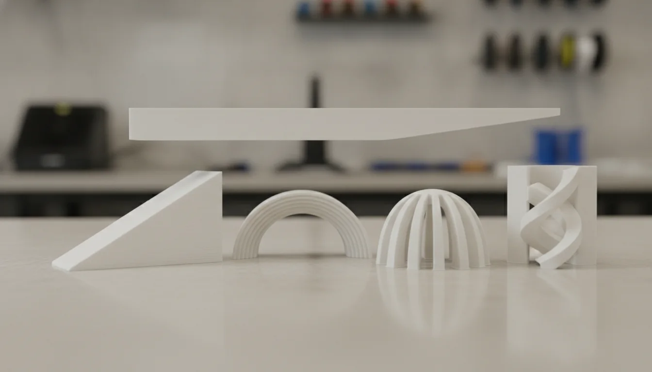
A bridge is fine where the underside is hidden or does not need to be flat. Where it does, shorten it: add an internal rib or wall that cuts one long span into two short ones, or design the roof of a cavity as an arch or a pitched roof instead of a flat ceiling.
Sacrificial layer for upside-down counterbores. A counterbore printed with the wide end down has a ring-shaped overhang around the small hole: it cannot bridge, because the hole is in the way, and support inside a hole is hard to remove. The fix described in the Rahix guide is to model a bridge one layer thick across the whole counterbore. The small hole then prints on top of it, and afterwards you cut or drill the thin layer out.
Stepped bridges, no cleanup. The same guide describes a cleverer version: in the first layer above the counterbore, bridge only two strips running either side of the small hole; in the next layer, bridge across those strips at 90°, which leaves a square the size of the hole; the round hole then prints on top of the square with only a tiny overhang. The hole stays open, so nothing needs cutting. The author notes it gets harder as the diameter grows.
If you do not want to change the CAD model, OrcaSlicer’s Bridge counterbore hole setting offers a partially bridge and a sacrificial layer option that generate these bridges at slicing time. Other small printed-in helpers work the same way: Prusa suggests modelling break-away supports into the part when a steep feature cannot be avoided.
Split the part or change its orientation
Some shapes have no orientation without large overhangs: a mushroom, a T-bracket, a figure with outstretched arms. Prusa’s guidance is that splitting a model into several parts can improve both its looks and its mechanical properties, because each piece can be placed in its best orientation. Protolabs Network adds that splitting can remove overhangs that would need a lot of support.
- Cut along a flat face so both halves get a flat side to print on.
- Add alignment features: pins and holes, a dovetail (the Rahix guide recommends dovetails because they print in most orientations), or screw bosses.
- Chamfer the mating edges so the parts slide together, and leave clearance between them: Prusa suggests starting at 0.3 mm for movable parts, Xometry gives 0.2–0.3 mm for a sliding fit.
Orientation decides more than overhangs. Prusa points out that a surface printed on the bed is flat and smooth, while one printed on supports is rougher, so put the face that matters on the bed. It also changes strength, because parts are weakest between layers; weigh that against overhangs using the guide to orientation for strength.
Common design mistakes
- Fillets on every edge. They look good in CAD, but on downward-facing edges they start with a flat overhang. Chamfer those.
- Teardrop pointing the wrong way. The point must face up in the print orientation. Check again if you rotate the part in the slicer.
- No clearance under a flat roof. Bridges droop a little; a roof that sits exactly on the hole circle makes the hole too tight.
- Designing to your own printer’s limit. A 70° overhang that works on a well-cooled printer may fail on someone else’s. For shared or sold models, stay near 45°.
- Refusing supports at any cost. Sometimes a few supports are the better answer. Use support enforcers and blockers to put them only where needed, or tree supports for scattered overhangs.
If a well-designed overhang still prints rough, the problem is on the slicer side: part cooling, overhang speed or temperature. The bridge and overhang slicer guide covers those settings. For a better surface above unavoidable supports, see support interface settings.
Frequently asked questions
What is the 45 degree rule in 3D printing?
It is the design guideline that an FDM printer can print an overhang up to 45° from vertical without supports. At that angle each new layer still rests on about half of the layer below. Many printers manage 60° or more with good cooling, but 45° is the safe value to design to.
Should I use a chamfer or a fillet for 3D printing?
Use a chamfer on horizontal edges that face down, including edges on the build plate, because a fillet there starts with a very steep overhang. Use fillets on vertical edges, where they let the nozzle round the corner smoothly. On top edges both work, but chamfers show more even layer lines.
How do I print horizontal holes without supports?
Give the hole a teardrop shape with a 90° point facing up, so no part of it is steeper than 45°, or cut the top flat and let it bridge, leaving a little extra clearance. Where the design allows, turn the part so the hole is vertical. A diamond-shaped hole also supports itself.
How long can a bridge be without supports?
Protolabs Network puts the limit for a bridge with no sagging or support marks at 5 mm. Printers can span longer gaps, but the underside droops and gets rougher as the span grows. Where the surface matters, shorten the span with a rib, or tune bridge cooling and speed in the slicer.
Sources
- Prusa Knowledge Base: Modeling with 3D printing in mind
- Protolabs Network: How to design parts for FDM 3D printing
- Xometry Pro: FDM 3D printing design tips
- 3D Print Academy: Designing for FDM production parts
- Rahix’ Blog: Design for 3D-printing (personal design guide)
- OrcaSlicer Wiki: Bridging settings