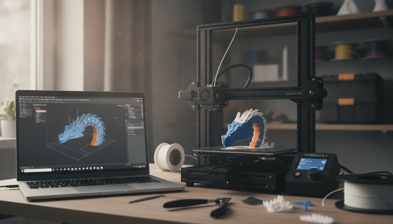
An export and slicing checklist is the short list of checks between finishing a model and pressing print: the right units, a suitable file format, a clean mesh, a sensible orientation and a preview you actually look at. For a first model, export in millimeters, use 3MF if your program and slicer both support it (otherwise binary STL), and read the model’s dimensions in the slicer before you slice anything.
Most first-print failures that look mysterious come from one of five causes: wrong scale, a damaged mesh, a faceted export, a bad orientation or a slicer profile for the wrong printer. This checklist covers each in order. The file-format facts come from the Library of Congress, the 3MF Consortium, Prusa’s documentation and Onshape’s help, linked at the end. Orientation, mesh repair and slicer tuning each have their own guides, which we link instead of repeating.
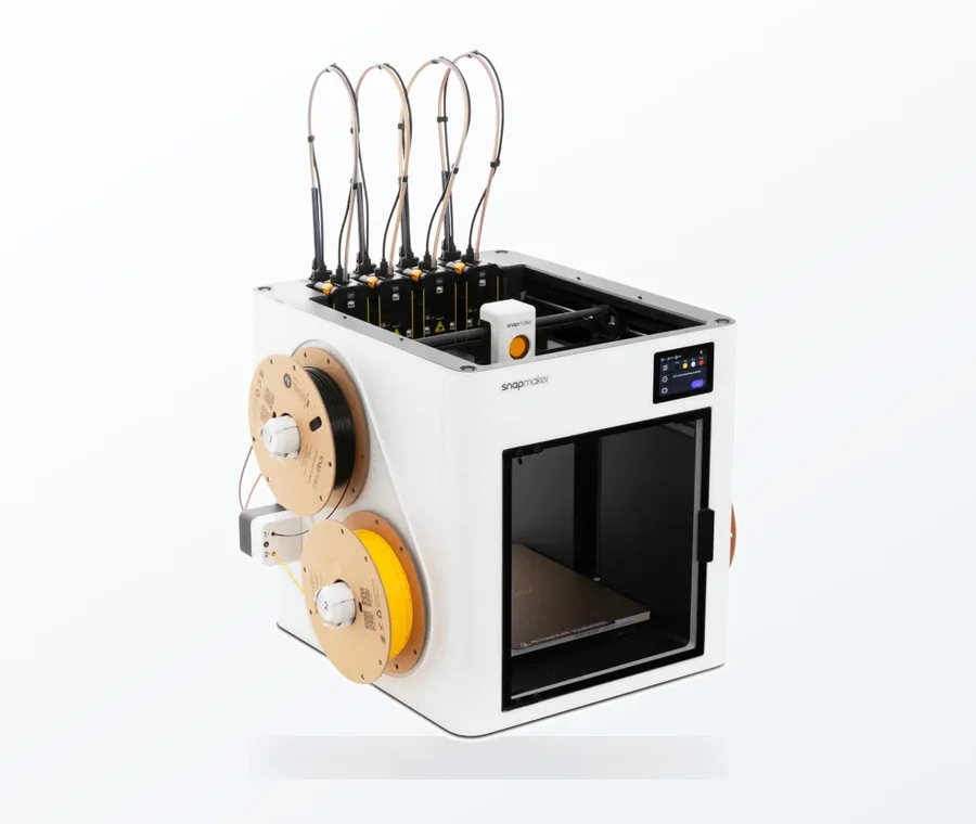
The consumer toolchanger 3D printer: the SnapSwap 4-toolhead system swaps heads in 5 seconds for true multi-color and multi-material printing, with smart calibration and auto filament loading.
- 4 toolheads · 5 s swap
- Up to 500 mm/s · 20,000 mm/s²
- 270 mm cube build volume
- Multi-color & multi-material
Export and slice checklist
- Units: set the modeling program to millimeters and export in millimeters.
- Format: 3MF if both programs support it; otherwise STL (binary is fine).
- Resolution: curves must look round in the slicer preview, not faceted.
- Scale check: read the bounding box in the slicer and compare it with your design.
- Mesh check: look for the warning symbol or error message when the file loads.
- Orientation: flat face down, fewest overhangs, layer lines away from the main load.
- Profile: printer, nozzle and filament profile match your actual hardware.
- Preview: scrub through the layers, then check time and material estimates.
Units and scale: the first thing to verify
An STL file does not state a unit for its coordinates, so the same file can mean millimeters or inches depending on what the modeler assumed. OBJ is the same: its coordinates have no units, although a file can carry scale information in a comment line. 3MF is different: its core specification defines units and coordinate systems.
That is why a part designed as 2 inches long can arrive 2 mm long. Prevent it at the source by choosing the unit in the export dialog. Onshape’s STL export, for example, lets you pick Centimeter, Foot, Inch, Meter, Millimeter or Yard, its OBJ export is in meters only, and STEP defaults to meters unless you tick the custom units option. In Tinkercad, check Units in the Workspace settings before you start modeling.
Then confirm in the slicer. PrusaSlicer reads incoming coordinates as millimeters and shows a prompt offering to treat a very small model as inches, a behavior Prusa forum users describe in several threads. Say yes only if you know the file is in inches. Otherwise the correct fix is to re-export with the right unit, not to scale the model by hand.
STL, 3MF, OBJ or STEP
| Format | What it keeps | Weak point | Use it for |
|---|---|---|---|
| STL | Triangle mesh only; no standard multi-color support. Binary is the common form, and most software reads both binary and ASCII | No unit stated | Single-material parts; the safe default |
| 3MF | Geometry plus units, color, materials and print settings in one file; recognized as an international standard in 2025 (ISO/IEC 25422:2025) | Not every program exports it | Several objects on one plate, or a project you want to reopen |
| OBJ | Geometry, with materials in a separate MTL file | No units; PrusaSlicer ignores material and texture on import | Meshes coming out of sculpting programs |
| STEP | Exact CAD solids in a neutral exchange format | PrusaSlicer triangulates it on import, so the slicer chooses the mesh resolution; most CAD software supports only part of the full STEP entity set | Keeping or sharing the editable solid, not as the print file |
Prusa’s file-format page calls 3MF the preferred format, also used to save project files, and suggests 3MF over AMF. A 3MF project saved from PrusaSlicer stores the plate and the settings, so it is the better format for reopening a print later. Keep your CAD or Tinkercad design as the editable master in every case. For more on how each modeling type produces these files, see the types of 3D modeling.
Mesh resolution: avoid faceted curves
Every curve in an STL is approximated by flat triangles, and the export settings decide how many. In Onshape, the STL export offers Coarse, Medium, Fine and Custom resolutions; Custom exposes the chordal tolerance, angular deviation and minimum facet width. Chordal tolerance is how far the triangles may deviate from the true surface, and a smaller value gives a finer mesh and a larger file. Other CAD programs have the same idea under names such as refinement, resolution or surface deviation.
A practical routine is to export at a medium setting, look at a hole or a round edge in the slicer preview, and tighten one step only if the curve looks faceted. If the file becomes very large or slow to load, loosen it. Do not export at the finest setting by default: detail finer than your nozzle and layer height cannot print, and the extra triangles only slow down loading. There is no universal value, so treat any number you read, including from old guides, as printer-dependent.
Check the mesh when it loads
A mesh can look fine on screen and still be damaged: gaps, flipped faces, or edges shared by more than two triangles. Slicers repair many problems automatically, often without telling you, but built-in repair has limits. In PrusaSlicer a warning symbol next to the model’s name flags a problem, and right-clicking it opens repair options.
Prusa’s help article also describes a Windows-only “Fix by the Netfabb” option, but readers’ comments on that page say the underlying service has been retired, so do not count on it. If automatic repair does not work, use a dedicated repair tool. Our guides cover the three common cases: the mesh errors checklist, non-manifold edges and closing holes in STL files. Models built from solid bodies in CAD are less prone to these problems, while meshes from sculpting or editing are more at risk.
Orientation and supports
Orientation decides layer direction, support volume and surface quality. Tinkercad’s own printing advice is to rotate the part so more of its surface touches the workplane and to avoid overhangs. Printed layers are weakest between layers, so a part that will be pulled apart should not have its layer lines running along the pull. The detailed rules, with strength examples, are in our guide to print orientation for strength. If the shape forces supports, the support-free design guide shows how to avoid them in the model.
Slicer import checks
- Bounding box: compare the width, depth and height shown in the slicer with your design. A factor of 25.4 off means inches and millimeters were mixed up.
- Plate fit: make sure the part sits fully on the build plate and nothing is hidden outside the visible area.
- Profile: confirm the printer, nozzle diameter and filament in the slicer match your machine. A profile for another nozzle size or bed will give wrong results that look like a filament problem.
- Preview: scrub through the layers and look for missing walls, floating islands, thin features printed as single lines and unsupported spans.
- Estimates: a time or material figure far above what you expected usually means a setting is higher than intended, or an extra object is hiding off screen.
Layer height, wall count and infill are slicer decisions rather than export decisions. Start from the default profile for your printer and filament, then read how to choose layer height and the infill guide when you need to change them.
Symptoms and what to check first
| Symptom | Likely cause | Fix |
|---|---|---|
| Model loads tiny or huge | Inches and millimeters mixed up | Re-export with the correct unit; do not scale by hand |
| Missing walls or holes in the preview | Damaged mesh | Repair the mesh, then re-slice; see the mesh checklist |
| Round holes look like polygons | Coarse export resolution | Re-export one resolution step finer |
| Slicer is slow or the file is huge | Resolution far finer than the printer needs | Re-export one step coarser, or simplify the mesh |
| Colors or multiple objects lost | Format cannot store them (STL) | Use 3MF, or set colors in the slicer |
| Part fails halfway | Orientation or support problem | Re-orient, then check the preview for unsupported spans |
After a first model prints, your next step is usually the first-layer settings; see first layer calibration. If you have not made a model yet, your first 3D model walks through one.
Frequently asked questions
Should I use STL or 3MF for 3D printing?
3MF is the better choice when your modeling program and your slicer both support it, because it stores units, colors, materials and print settings. STL is the universal fallback: it stores only a triangle mesh with no unit, so you must confirm the size in the slicer. PrusaSlicer reads both and calls 3MF its preferred format.
Why did my model import at the wrong size?
An STL file does not carry a unit, so the slicer normally reads the numbers as millimeters. If the model was built in inches it appears about 25 times too small. Re-export from your program with millimeters selected rather than scaling the model in the slicer.
Is binary or ASCII STL better?
Binary is more compact and is the more common form, and most software that reads STL reads both. Choose binary unless a tool specifically asks for ASCII. The geometry is the same; what matters for quality is the export resolution.
How fine should my STL export resolution be?
Fine enough that curves look round in the slicer preview, and no finer. Details smaller than your nozzle and layer height cannot print, so a very fine export mainly adds file size. Export at a medium setting first and tighten one step if you see facets.