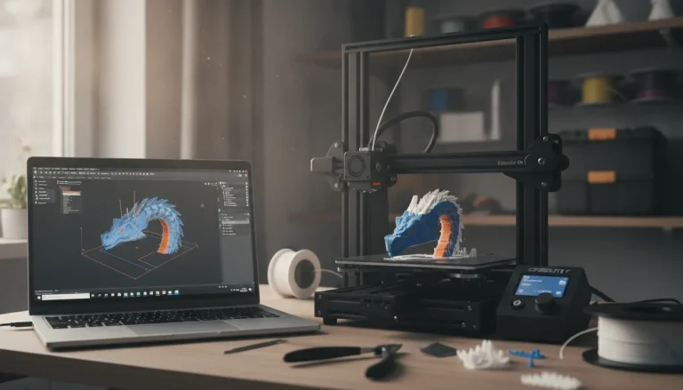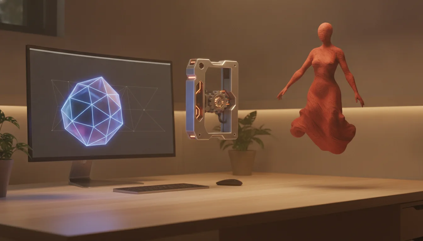
The types of 3D modeling differ in how a program stores a shape: as a surface mesh of flat faces (polygonal modeling and sculpting), as exact solid geometry built from sketches and features (CAD, usually parametric), or as a mesh captured from a real object (scanning). For 3D printing, use CAD when a part must fit real hardware, mesh or sculpting tools when the shape is organic, and scanning when you need a copy of something that exists.
Whatever you pick, the slicer receives a mesh, so the choice is about how you create and edit the shape, not about what the printer accepts. This guide compares the types, what each is good and bad at for printing, example programs, and the file formats involved. Program features are described from the vendors’ own documentation or, for the general concepts, Wikipedia as of 2026. For choosing an actual program, see our free modeling software comparison.
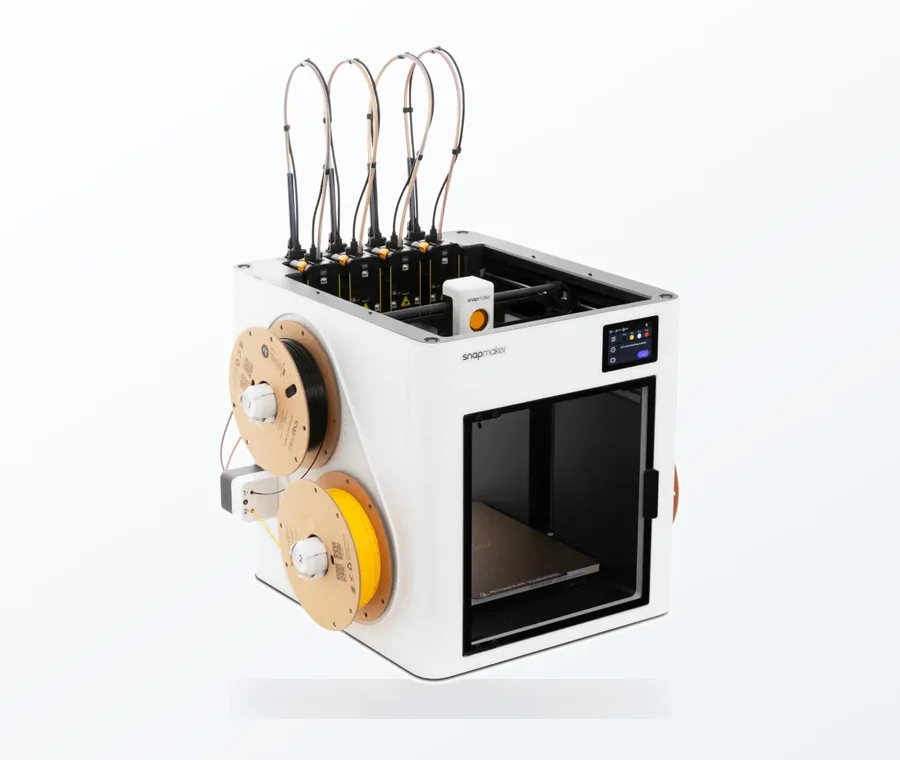
The consumer toolchanger 3D printer: the SnapSwap 4-toolhead system swaps heads in 5 seconds for true multi-color and multi-material printing, with smart calibration and auto filament loading.
- 4 toolheads · 5 s swap
- Up to 500 mm/s · 20,000 mm/s²
- 270 mm cube build volume
- Multi-color & multi-material
Which type fits your project
- A part that must fit something real (bracket, enclosure, adapter, replacement clip): solid or parametric CAD.
- A figure, bust, prop or creature with no exact dimensions: polygonal modeling or sculpting.
- A copy of an existing object: 3D scanning, then clean-up of the mesh.
- Something simple and quick from basic shapes: a block-based tool such as Tinkercad, which works like very simple solid modeling.
| Type | How the shape is stored | Good for printing | Weak at | Example programs |
|---|---|---|---|---|
| Polygonal (mesh) | Vertices, edges and faces (triangles, quads, n-gons) | Stylized models, props, quick forms | Exact, editable dimensions | Blender |
| Sculpting | A dense mesh deformed with brushes | Organic shapes, figures, surface detail | Mechanical parts; files are heavy | Blender Sculpt Mode, ZBrush |
| Solid CAD (parametric) | Closed solids built from sketches and features, with dimensions kept as parameters | Parts that fit hardware, easy revisions | Free-form organic shapes | Onshape, Fusion, FreeCAD |
| Scanning | A point cloud or mesh captured from a real object | Copies of real objects | Sharp edges and exact dimensions; needs clean-up | Scanner or photogrammetry software |
Polygonal (mesh) modeling
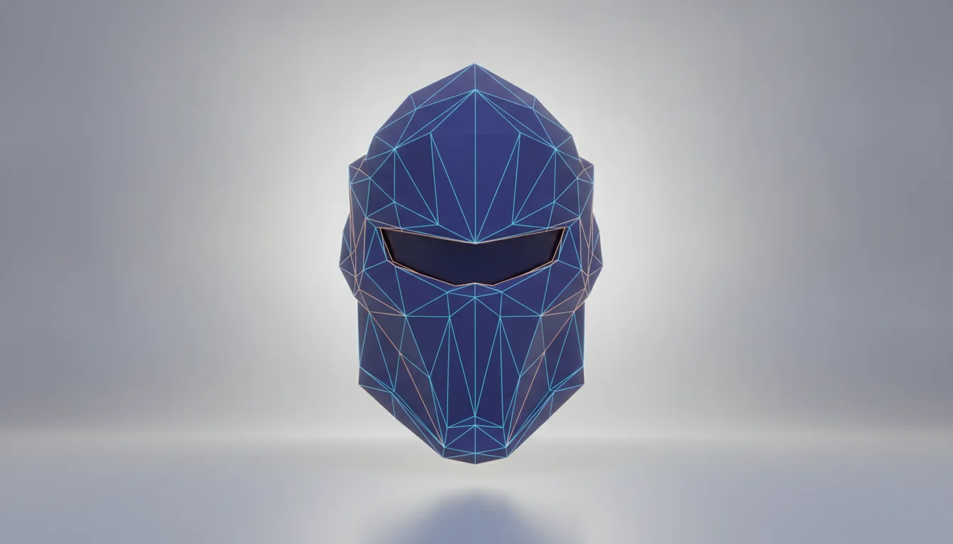
A polygon mesh is a collection of vertices, edges and faces that defines the surface of an object. In Blender’s manual, a face is the area between three (triangles), four (quads) or more (n-gons) vertices, and everything in a mesh is built from those three elements. You block the shape out with primitives, then add detail in Edit Mode with tools such as extrude and bevel.
This is how most STL and OBJ files are structured, so mesh modeling is closest to what the slicer reads. The cost is that a mesh has no sketch history or editable parameters, so changing a hole from one diameter to another means editing geometry, not typing a number. A mesh only describes the outer surface, which is also why it can contain gaps, flipped faces or intersections that a solid model cannot. When a slicer reports problems, the fixes are in our mesh errors checklist.
Solid and parametric CAD modeling
Wikipedia defines solid modeling as a consistent set of principles for mathematical and computer modeling of three-dimensional shapes, where a solid is a closed, bounded region that stays valid under Boolean operations. Parametric modeling adds parameters, such as dimensions, that define the model: change a parameter and the model, and anything built on it, updates. Constraints such as parallel sides define relationships between shape elements.
In practice you draw a 2D sketch, then turn it into 3D with features. In Onshape, for example, sketches are 2D geometry in a Part Studio and feature tools such as Extrude and Fillet turn them into parts. This is the natural home for brackets, enclosures, jigs and replacement parts, because every dimension can be changed later. Its weakness is organic form: a face or a flowing drape is slow to define with sketches. Our parametric shelf tutorial shows how editable dimensions pay off, and building a toy in Tinkercad shows the simpler block-based approach.
NURBS surfaces are another CAD representation: a mathematical model of curves and surfaces widely used in CAD, CAM and CAE software. They are exact, but a printer cannot use them directly, so the program converts them to a triangle mesh when you export.
Digital sculpting
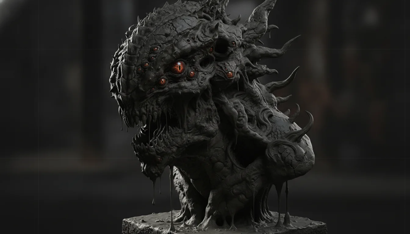
In Blender, Sculpt Mode is similar to Edit Mode in that it changes the shape of a model, but it works with brushes on an area of the model instead of individual vertices, edges and faces. Because brushes need enough geometry, Blender offers adaptive methods. The Voxel Remesher rebuilds the mesh with evenly distributed topology and produces a manifold volume, but it needs an enclosed volume, so holes must be filled first. Dyntopo adds and removes topology under the brush, at the price of slower performance and lost custom attributes such as UV maps and colors. Multiresolution sculpting works best on a clean base mesh of quads.
For printing, a sculpt has to be turned into a clean, closed mesh. Blender’s Decimate modifier reduces the vertex and face count of a mesh with minimal shape changes and is aimed at meshes that came from sculpting or subdivision. Reduce only as far as the printed detail allows: details smaller than your nozzle or layer height will not print anyway. For printing a sculpt see our sculpting block-out guide, and for ways to reduce a heavy file see STL mesh decimation. If you want to compare the free tools first, read Blender vs ZBrushCoreMini.
3D scanning
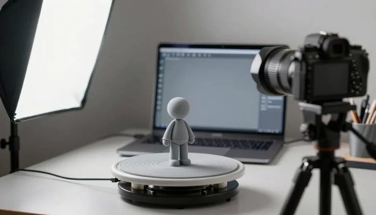
A 3D scanner produces a polygon mesh or a point cloud of samples on the surface of the subject. Several scans from different directions are usually brought into a common reference system and merged, and the resulting meshes are often very large and hard to edit. Where exact dimensions matter, reverse engineering converts a triangulated mesh into NURBS surfaces or a parametric CAD model. For printing a scan unchanged, expect to close holes and repair the mesh first.
File types by modeling type
Every type ends in a file the slicer can read. The formats differ in what they keep:
| Format | What it stores | Units | Typical source |
|---|---|---|---|
| STL | A triangular mesh only; no standard way to store multiple colors. Binary is more common and more compact than ASCII | No unit stated in the format | Every modeling type; the common denominator |
| OBJ | Geometry, with materials in separate MTL files | No units; scale information may sit in a comment | Mesh and sculpting programs |
| 3MF | Geometry plus materials, color and print settings in one file | Defines units and coordinate systems | Slicers and newer CAD tools |
| STEP | Neutral CAD exchange format; most CAD software does not support the full set of STEP entries | Depends on the export setting | Solid CAD models, for editing in another CAD program |
PrusaSlicer, for example, calls 3MF its preferred format, accepts binary and ASCII STL, triangulates STEP files on import and ignores material and texture data in OBJ. Keep the original CAD or sculpt file as your editable master and treat STL or 3MF as the output. Units and export settings are covered in the export and slicing checklist.
Mixing types and common mistakes
Many projects use two types: model the mechanical interface in CAD, sculpt organic details on a mesh and combine the meshes before export. Because CAD solids and meshes are different representations, the CAD part has to be exported as a mesh before it can be merged with a sculpt.
- Sculpting a part that has to fit. A sculpted bracket has no dimensions to tune after a test print. Use CAD for fit-critical features.
- Printing a raw sculpt. Dense meshes load slowly and can carry holes and intersections. Reduce, close and check the mesh first.
- Forcing a scan into a CAD workflow. A scan is a mesh; converting it to editable CAD geometry is a reverse-engineering job, not a button.
- Learning three programs at once. Pick the type that matches your first real project and finish one printable object. Your first 3D model walks through that with one example.
Frequently asked questions
What is the best type of 3D modeling for 3D printing?
There is no single best type. Solid or parametric CAD suits parts with exact dimensions that must fit real hardware, while polygonal modeling and sculpting suit organic shapes such as figures. All of them end as a mesh file for the slicer.
Can I use Blender for functional parts?
You can, since Blender is a mesh modeler and can export STL. But a mesh has no parametric history, so revising a dimension means editing geometry by hand. For parts that must fit, a CAD program such as Onshape lets you change a number in the sketch and update the model.
Do I need to reduce the polygon count of a sculpt before printing?
Often yes. A very dense sculpt is slow to load and has more detail than a printer can reproduce. Blender’s Decimate modifier reduces the face count with minimal shape change; reduce moderately and check the preview in your slicer.
Which file should I export from CAD: STL or STEP?
Export STL or 3MF for printing and STEP when you want to edit or share the solid in another CAD program. STEP keeps the CAD geometry, while a printing mesh cannot be edited like a sketch. Keep the original CAD file as your master either way.
Sources
- Blender Manual: Mesh Structure, Sculpting: Adaptive Resolution, Decimate Modifier
- Onshape Help: Sketch
- File formats: Library of Congress, STL format description, 3MF Consortium, Prusa Knowledge Base, supported file formats
- General concepts (Wikipedia, encyclopedia-level sources): solid modeling, NURBS, 3D scanning, OBJ files, STEP files