A first 3D model for printing is a simple part, such as a small clip, that you measure on the real object, build from four basic operations (sketch, extrude, boolean cut and fillet) and export as an STL or 3MF file for your slicer. The route is always the same: measure, sketch with numbers, set the program to millimeters, model, check the walls, export, slice and print a small test.
This guide walks through that route with one example part, a snap-in cable clip, in a way that works in Tinkercad, Autodesk Fusion and Onshape. Every dimension is an example to replace with your own measurements, and tool names come from the vendors’ help pages (checked in 2026). Which program to install is a separate question, covered in our free modeling software comparison.
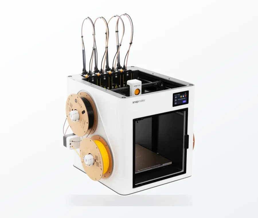
The consumer toolchanger 3D printer: the SnapSwap 4-toolhead system swaps heads in 5 seconds for true multi-color and multi-material printing, with smart calibration and auto filament loading.
- 4 toolheads · 5 s swap
- Up to 500 mm/s · 20,000 mm/s²
- 270 mm cube build volume
- Multi-color & multi-material
First 3D model in seven steps
- Measure the object the part must fit, with calipers, in millimeters.
- Sketch the part on paper and write every dimension on it.
- Set your program to millimeters before you draw anything.
- Build the main shape: a sketch extruded to a thickness, or a box in Tinkercad.
- Cut features with a boolean cut: holes, slots and pockets.
- Round the corners with a fillet, then check wall thickness and orientation.
- Export STL or 3MF, confirm the size in the slicer and print a small test.
The example part: a snap-in cable clip
The clip is a block with a round channel for one cable and a narrow slot on top, so the cable can be pressed in from above. It is a good first part because it has one measured dimension that matters (the cable), one hole, one cut and no overhangs when it prints with its flat face on the bed.
| Feature | Example value | Why this value |
|---|---|---|
| Cable diameter | 4.0 mm | Caliper reading on the real cable. Replace with yours. |
| Channel diameter | 4.4 mm | Cable plus 0.4 mm clearance. A university makerspace guide for Prusa MK4 and XL printers lists 0.30–0.40 mm for separate parts; treat it as a starting point and test. |
| Snap slot width | 3.2 mm | Narrower than the cable so it presses in. Adjust after a test print. |
| Block profile | 16 × 10 mm, 12 mm thick | Leaves 5.8 mm of material beside the channel and 2.8 mm under it. |
| Corner fillets | 2 mm | Rounds the four outside corners; cosmetic and more comfortable to handle. |
Check the wall math before you model: the channel center sits 5 mm above the bottom edge, so the material under it is 5 − 2.2 = 2.8 mm. Tinkercad’s own printing advice is to keep walls at 1.5 mm or thicker, and every wall in this part clears that.
Measure and sketch with numbers first
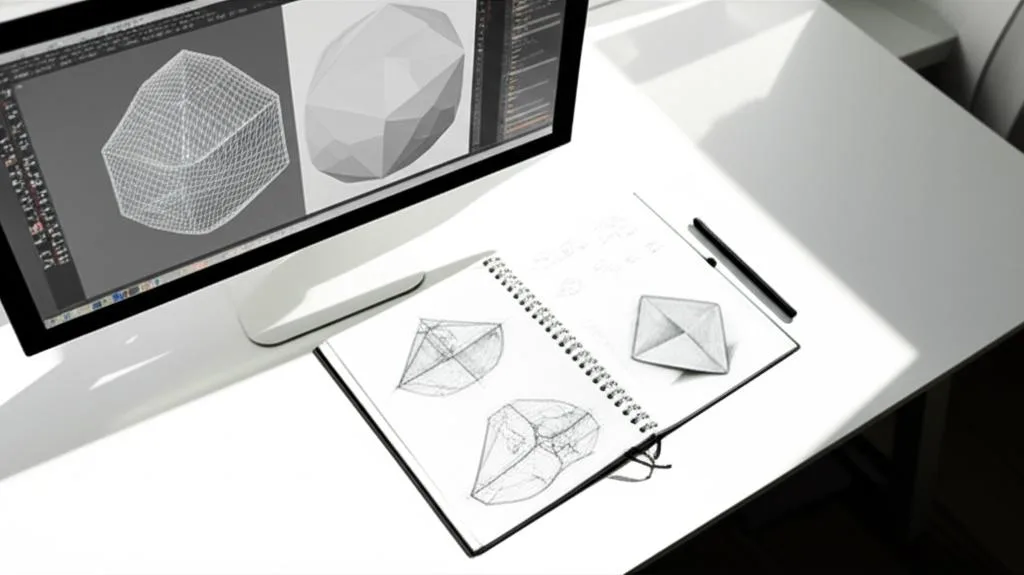
Model from numbers, not by eye. Measure the real object at two or three places, because cables, tubes and edges are rarely uniform, and write the readings on a paper sketch. Mark which dimensions mate with something real (the cable, a shelf edge, a screw) and which are only cosmetic. Those mating dimensions are the ones you will later adjust after a test print, so keep them easy to find.
For anything that is not symmetric, sketch a front and a top view. The first sketch you draw in CAD is exactly one of those views, so the paper version saves you from solving two problems at once: what the part looks like, and how the software works. Skip textures, UV maps, lighting and rendering, which belong to games and film. A printer needs geometry only, and PrusaSlicer, for example, ignores material and texture data in OBJ files on import.
The four tools every program has
Underneath different menus, nearly every modeler uses the same small set of operations. Learn these four and you can follow most tutorials in any program.
| Operation | What it does | Tinkercad | Autodesk Fusion | Onshape |
|---|---|---|---|---|
| Sketch | Draws a flat 2D profile on a plane | No sketch step: you start from basic shapes | Sketch on a plane or face | Sketch on the Top, Front or Right plane (or one you create) |
| Extrude | Pushes a closed profile into a solid of a set thickness | Set the shape’s height with the handles or typed dimensions | Extrude, with Distance as the extent type | Extrude, with a Blind end type and a depth |
| Boolean cut | Removes one shape’s volume from another | Turn a shape into a Hole, then Union Group (Ctrl/Cmd+G) | Extrude with Operation: Cut, or the Combine command | Extrude with Remove, or Through all for a hole |
| Fillet | Rounds an edge with a radius | No fillet tool in the help pages; skip it on a first model | Fillet with a radius type such as Constant | Fillet with a radius |
| Join or intersect | Merges bodies, or keeps only the overlap | Union Group; Intersect group in the Inspector | Join and Intersect operations | Add and Intersect results |
For more on cutting and merging shapes, see our guide to boolean operations. Fusion also lets you merge existing bodies afterwards with Combine: Join merges them, Cut subtracts the tool bodies and Intersect keeps the overlap.
Build the clip step by step
- Start the file and set units. In Tinkercad, open the Workspace settings at the bottom right and check Units and the Snap Grid, which defaults to 1 mm. In Fusion and Onshape, check the unit setting of the document before drawing.
- Make the block. In Fusion or Onshape, sketch a 16 × 10 mm rectangle on the top plane and extrude it 12 mm. In Tinkercad, drag in a Box and size it 16 × 10 mm with a height of 12 mm, so the 16 × 10 face sits on the workplane.
- Add the channel. Draw a 4.4 mm circle 5 mm in from the front edge, centered across the 16 mm width. In Fusion extrude it with Operation: Cut, in Onshape with Remove. In Tinkercad, drag in a Cylinder, size it 4.4 × 4.4 mm and make it taller than the block (for example 14 mm), switch it to a Hole in the Inspector, then use the Align tool to center it and the Ruler tool to set its distance from the edge.
- Add the snap slot. Draw a 3.2 mm wide rectangle from the channel to the top edge and cut it through the full 12 mm in the same way (in Tinkercad, a hole Box).
- Combine and check. In Tinkercad, select everything and press Union Group; the preview then shows the real shape with the channel cut out. In Fusion and Onshape the cut is already part of the body.
- Round the outside corners. Select the four outside edges that run along the 12 mm thickness and apply a 2 mm fillet. Do not fillet the channel edges: you want a clean, predictable opening.
- Measure. Confirm the overall size is 16 × 10 × 12 mm and the channel is 4.4 mm before you export.
Tinkercad has no fillet in the help pages we checked, so a square-cornered clip is fine for a first model. The shape works in any program because it is one sketch, one extrude, two cuts and one fillet.
Check the model before you export
| Check | Guideline | Source or status |
|---|---|---|
| Wall thickness | At least 1.5 mm; avoid parts or walls that are too small or thin | Tinkercad printing best practices |
| Floating parts | Everything touches the workplane, nothing hovers above it | Tinkercad printing best practices |
| Overhangs | Avoid them, and rotate the part so more of its surface lies on the workplane | Tinkercad printing best practices; see design for support-free printing |
| Clearance for mating parts | Start around 0.3–0.4 mm for separate parts, then test | University makerspace guide for Prusa MK4/XL; printer-dependent |
| Hole size | Printed holes can come out smaller than designed; print a small test of just the hole | General FDM behavior; test on your own printer |
Export, then slice
Tinkercad’s Export button on the top toolbar offers OBJ, STL and GLTF, and it can export everything or only the selected shapes. It groups all shapes into a single part on export, so check your holes first. Onshape and Fusion export from their own export dialogs; choose millimeters, because an STL file does not record units.
Keep the original design file as your master. A mesh file such as STL cannot be edited like a sketch, so for any part you may revise, keep the CAD document too. Then open the STL or 3MF in your slicer and read the model dimensions before slicing: 16 × 10 × 12 mm is what you should see. The full pre-slice routine, including formats, scale and orientation, is in our export and slicing checklist. If the slicer complains about holes or non-manifold edges, use the mesh errors checklist.
Print the clip with its 16 × 10 mm face on the bed, so the channel prints as a round hole standing upright. Then press a cable in. If it is loose, reduce the channel by 0.1 mm; if it will not enter, widen it by 0.1 mm and reprint. This fit-test loop is normal for any part that mates with something real.
What if you do not want to model at all?
You can print downloaded files, scans and generated shapes without modeling anything yourself, but each of those is still a 3D model; the slicer needs one to cut into layers. Basic modeling skills matter even then, because downloaded files often arrive at the wrong size, need a hole enlarged or a flat base added, or have mesh errors that only show in the slicer. A part that must fit your own hardware is usually faster to model than to search for.
To go further after this clip, the types of 3D modeling explains when mesh, CAD or sculpting suits a project, and our Tinkercad toy tutorial is a good second project.
Common first-model mistakes
- Starting with something complicated. A character or a vehicle hides ten new skills in one project. One measured, single-purpose part teaches the same tools.
- Wrong units. A model built in inches and read as millimeters arrives about 25 times too small. Set millimeters first and confirm the size in the slicer.
- Modeling by eye. If the part has to fit something, the measurement goes on the sketch before the software opens.
- No clearance. Two printed surfaces designed to the same nominal size will not fit. Add clearance and test the fit with a small piece before printing a large one.
- Overusing fillets. Rounding every edge removes the flat faces that sit on the bed or register against another part. Round what you touch, leave the rest.
Frequently asked questions
What is the easiest first thing to model for 3D printing?
Pick one useful part with two or three measured dimensions, such as a cable clip, a spacer, a label tag or a stand. It forces you to use sketching, extruding, cutting and units, and it is small enough to reprint quickly if the fit is off.
Do I need to learn 3D modeling to use a 3D printer?
No, you can print files you download, but you still depend on someone else having made a model that fits your needs and your printer. Basic modeling lets you scale, modify and repair files, and design parts that mate with your own hardware.
Should I export STL or 3MF for my first model?
Either works. STL stores only a triangle mesh without units, so confirm the size in your slicer. PrusaSlicer calls 3MF its preferred format and supports binary and ASCII STL, so use 3MF if your program offers it and STL if it does not.
Why is the printed hole smaller than the one I modeled?
Printed holes often come out slightly undersized, so a hole modeled at exactly the cable or pin diameter is too tight. Add clearance (0.3–0.4 mm is a published starting point for separate parts on Prusa printers), print a small test of just the hole and adjust by 0.1 mm.
Sources
- Tinkercad Help: Best Practices for 3D Printing Tinkercad Models
- Tinkercad Help: Exporting 3D models for 3D Printing
- Onshape Help: Extrude
- Autodesk Fusion Help: Extrude reference
- University of Florida Makerspace: Designing for 3D printing tolerances on the MK4 and XL
- Prusa Knowledge Base: Supported file formats