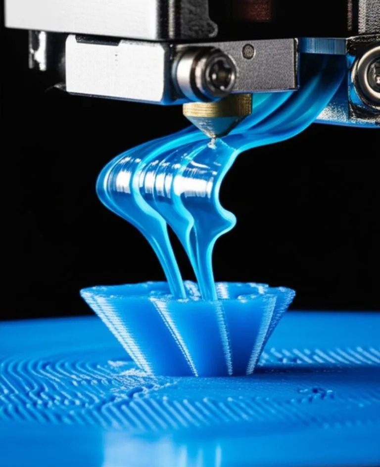
Part cooling is the stream of air a fan and duct blow onto freshly extruded plastic so it solidifies before the next layer or the next bridge strand lands on it. For PLA the fan normally runs on, up to full speed. PETG needs less (Prusa uses half power after the first layers, Polymaker says off to 20%), and ABS, ASA and PC want it off or very low. A better fan only helps if the duct aims well and the slicer settings match the material.
This guide covers what to set per material, how the main slicer cooling options work, how axial fans differ from 5015 blowers (with one maker’s datasheet figures), what to check before swapping a fan, and a symptom table. Settings come from Prusa, Polymaker, OrcaSlicer, Marlin and Klipper documentation, linked at the end. Where a value is only a starting point, it says so.
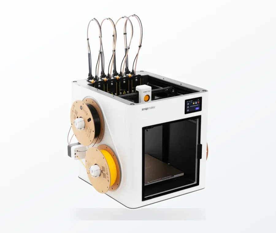
The consumer toolchanger 3D printer: the SnapSwap 4-toolhead system swaps heads in 5 seconds for true multi-color and multi-material printing, with smart calibration and auto filament loading.
- 4 toolheads · 5 s swap
- Up to 500 mm/s · 20,000 mm/s²
- 270 mm cube build volume
- Multi-color & multi-material
Part cooling in 60 seconds
- Fan off for the first layer or few layers (Prusa says roughly 1 to 5, depending on the filament), then ramp up.
- PLA: fan on, start at 100% and back off only if layers split. PETG: about 50% (Prusa) or less. ABS, ASA, PC: off.
- Raise the fan only for bridges and overhangs (Prusa’s “Bridges fan speed”, Orca’s “Force cooling for overhangs and bridges”) so the rest of the part keeps its layer bonding.
- For tiny layers, enable “slow down if layer time is below” so each layer has time to set.
- Upgrade hardware last: check duct aim, fan voltage and the fan header’s current limit before buying a bigger blower.
Fan settings by material
Cooling is a trade-off. More air gives sharper overhangs, cleaner bridges and less stringing; less air lets layers stay hot enough to fuse. Prusa says as much for PETG: for maximum toughness, turn the print fan off, and accept worse overhangs and bridges. Use the table as a starting point and adjust on your own printer.
| Material | What the maker says | Source |
|---|---|---|
| PLA | Cooling fan “on” (Polymaker PolyLite PLA, 0.4 mm nozzle). No percentage given; 100% is the usual starting point. | Polymaker data sheet |
| PETG | Fan off for the first layers, then 50%. Fan off for maximum toughness. Polymaker PolyLite PETG: off to 20%. | Prusa KB; Polymaker data sheet |
| ABS | Fan off (PolyLite ABS, enclosure required). Prusa: no draft around the print. | Polymaker data sheet; Prusa KB |
| PC | “Keep cooling fans off” (PolyLite PC, heated chamber recommended). | Polymaker data sheet |
| TPU | Fan “on” (PolyFlex TPU95, 30 to 50 mm/s). Makers’ sheets differ between TPU grades, so check your spool. | Polymaker data sheet |
| ASA, nylon | Not checked here. Use the maker’s data sheet; ASA is usually handled like ABS. | Check your spool |
Prusa’s slicer notes add that “keep fan always on” is typically enabled except for ABS, ASA, PC and some flexible filaments. For warping and enclosure advice on those materials, see printing ABS without warping, and for PETG fan, retraction and stringing together, PETG print settings.
Slicer cooling settings that matter
PrusaSlicer and OrcaSlicer expose the same ideas under slightly different names. Neither documentation page gives default percentages, so treat all numbers as yours to tune.
| Idea | PrusaSlicer (Filament, Cooling) | OrcaSlicer (Material, Cooling) |
|---|---|---|
| First layers without fan | Disable fan for the first N layers | No cooling for the first layers |
| Ramp-up | Fan speed min and max | Full fan speed at layer (linear ramp up to maximum) |
| Fan stays running | Keep fan always on | Keep fan always on |
| Short layers | Enable fan if layer time is below; Slow down if layer time is below; Min print speed | Fan speed threshold; Slow printing down for better layer cooling; Min print speed |
| Bridges and overhangs | Bridges fan speed (overrides the fan on bridges and overhangs; set higher than normal) | Force cooling for overhangs and bridges, with overhang cooling threshold (0%, 10%, 25%, 50%, 75% or 95% unsupported line width) and separate overhang and internal-bridge fan speeds |
Some details from the docs that save trial and error:
- Layer-time cooling. Prusa’s min/max fan speeds are percentages of the fan’s maximum. Max applies to short layers, min to long ones, and values in between scale proportionally. The slow-down option stretches a short layer to the time you set. Prusa warns that very low speeds for long periods can cause heat creep, so do not set the min print speed too low.
- Internal bridges. In Orca, the internal bridge fan speed can be set separately (or -1 to follow the overhang speed). Lower values can reduce warping from prolonged cooling over big areas.
- Support interfaces. A higher fan speed there weakens the bond between support and part, which makes the support easier to remove.
- Fan start-up lag. Orca can start the fan a set number of seconds before it is needed (“fan speed-up time”) and can kick-start a fan with a burst of full speed. This helps when a fan takes a moment to spin up before an overhang.
- Bridge speed too. Prusa recommends a lower speed and lower bridge flow for bridges. Slicer-side bridge tuning is covered in sagging bridges and overhangs.
Firmware: how the fan speed reaches the fan
The slicer writes a fan command and the firmware turns it into PWM. In Marlin, M106 S<0-255> sets the speed (S255 is 100%), P<index> selects another fan, and an M106 without S runs the fan at full speed. In Klipper, the [fan] section has these useful options: max_power (default 1.0), off_below (the lowest speed that powers the fan, default 0.0), kick_start_time (default 0.100 s at full speed when the fan starts or rises by more than 50%) and cycle_time (default 0.010 s).
Many fans stall at low PWM. If a 10% command does nothing, set the minimum in one place: Orca’s “minimum non-zero part cooling fan speed” raises any non-zero command to that floor, and its wiki recommends matching it to Klipper’s off_below if you use that.
Axial fans vs 5015 blowers
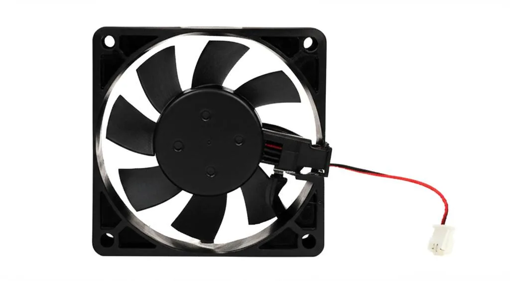
An axial fan moves air parallel to its shaft: high volume, low pressure. A centrifugal blower pressurises air in a scroll housing and exhausts it at 90 degrees to the intake: higher pressure at lower volume, according to a Digi-Key fan guide. Part cooling pushes air through a narrow duct, which is why most printers use blowers there. Axial fans suit open airflow, such as heatsink fans.
The name “5015” refers to a blower roughly 50 x 50 x 15 mm. Specifications vary by maker, so read the datasheet for the exact part. One example: the Mechatronics B5015E24B-BSR (Digi-Key listing) is 51 x 51 x 15.7 mm, 24 V, 0.18 A, 6,500 rpm, 5.0 CFM (0.14 m³/min) with 219.2 Pa (0.88 in H2O) static pressure, 45 dB(A) and a ball bearing. Those are the maker’s maximum figures for that part, not what you will get through a restrictive duct.
| Check | Why it matters |
|---|---|
| Rated voltage (12 V or 24 V) | Match the printer’s fan output. A fan fed far above its rating can be damaged; one fed below it will run slower or may not start. A buck converter is the usual fix for a mismatch. |
| Current | Compare it with the fan header’s limit in your board’s documentation. Two fans draw the sum of both currents; if it exceeds the header rating, drive them from an external MOSFET module instead. |
| Static pressure, not just CFM | The duct restricts the flow, so a blower’s pressure rating tells you more than its free-air flow. |
| Bearing and noise | The sample above has a ball bearing and 45 dB(A). Datasheets list both. |
| Tachometer wire | Optional; Klipper’s tachometer_pin can monitor speed. |
Ducts: where the air actually goes
The duct decides whether a strong fan helps. A single-sided duct cools the side facing it first, which can leave one edge of a bridge or overhang less cooled. Dual-sided ducts aim for a more even result by blowing from both sides. That is a general design principle, not a guarantee: results depend on the specific duct and how well it is aimed.
- Aim. Point the outlet at the nozzle tip, just below it, without blowing on the heater block. Air on the block cools it and can make the temperature drop whenever the fan speeds up; Marlin offers optional fan scaling for PID (
PID_FAN_SCALING) and MPC for exactly this case. - Material. Print the duct in a material that tolerates heat near the hotend. Prusa warns that an enclosure can deform the fan shroud and other plastic parts, and suggests a more heat-resistant material such as its PC Blend.
- Clearance. The duct must not drag on finished parts or block the nozzle’s view of the print.
- Weight. A heavier toolhead can change ringing. After adding fans and a duct, print a ringing test and re-check; see ringing and ghosting.
Symptom table
| Symptom | Likely cause | Try |
|---|---|---|
| Bridges sag | Too little cooling, bridge too fast or too much flow | Raise bridge fan, lower bridge speed and flow (Prusa) |
| Overhang edges curl up | Plastic still soft; weak or one-sided airflow | Overhang fan up; check duct aim; slow down short layers |
| Layers split or part snaps between layers | Too much cooling for the material | Lower fan; for PETG try 50% or less; raise nozzle temperature a little |
| Corners lift on ABS, ASA, PC | Fan on, draft or cold ambient air | Fan off, enclosure, no draft |
| Stringing on PLA | Too little cooling or too hot | Check the fan really runs; then temperature and retraction |
| Fan runs at 100% but nothing changes | Fan stalls at low PWM, blocked duct, wrong voltage | Set a minimum fan speed; clean the duct; verify wiring |
| Small parts blob and melt | Layer time too short | Enable the slow-down below layer time |
Mistakes and next steps
- Buying a bigger fan before checking the duct. A blocked or badly aimed duct wastes any fan. Check airflow at the nozzle with the fan at 100% first.
- Using one fan setting for every filament. Keep separate filament profiles for PLA, PETG and ABS.
- Cooling the first layer. It works against adhesion; Prusa says it is usually not necessary. If prints lift, see prints not sticking to the bed.
- Chasing a bridge problem with hardware alone. Design changes often cost nothing; see designing for support-free printing.
Frequently asked questions
What fan speed should I use for PLA and PETG?
For PLA, Polymaker’s data sheet says the fan should be on, and 100% is the usual starting point, lowered if layers split. For PETG, Prusa keeps the fan off for the first layers and then runs it at 50%; Polymaker’s PolyLite PETG sheet says off to 20%. Test on your printer and filament.
Is a 5015 blower better than a stock part cooling fan?
Only if the duct, voltage and wiring suit it. A blower delivers higher pressure than an axial fan, which helps push air through a duct, but your stock fan may already be a blower of similar size. Compare datasheet pressure figures, not just the size name, and check the board’s fan header current limit.
Can I use a desk fan to cool prints?
For PLA on an open printer, extra airflow can help, but it is uneven and can cool one side faster. For ABS, ASA and PC it is a risk: Prusa says not to create a draft around the print. Use the duct and slicer settings for anything that matters.
Why does turning the fan up make PETG weaker?
Fast cooling reduces how well layers fuse. Prusa says that higher filament temperature improves layer merging and that, for maximum toughness, you can turn the print fan off, at the cost of bridges and overhangs.
Sources
- Prusa Knowledge Base: Cooling (PrusaSlicer filament settings)
- Prusa Knowledge Base: PETG, ABS and Bridging
- OrcaSlicer wiki: Material cooling and Cooling fan
- Polymaker data sheets: PolyLite PLA, PETG, ABS, PC
- Klipper configuration reference ([fan]) and Marlin M106
- Digi-Key: Comparing axial and centrifugal fans and Mechatronics B5015E24B-BSR listing