To install a BLTouch or CR Touch, mount the probe so its retracted pin sits a few millimetres above the nozzle tip (ANTCLABS specifies 2.3–4.3 mm for the BLTouch), plug it into the probe port or the servo and Z-min pins, and flash firmware with probe support. Then measure the X/Y offset between nozzle and pin, set the Z-offset with a sheet of paper, and fine-tune it on a first-layer test print. Save everything, and load the bed mesh from your start G-code.
The steps and values below come from the ANTCLABS BLTouch manual, Creality’s CR Touch manual and the Marlin and Klipper documentation, all linked at the end. Menu names and pin assignments change between boards, so check your own board’s pinout before you plug anything in.
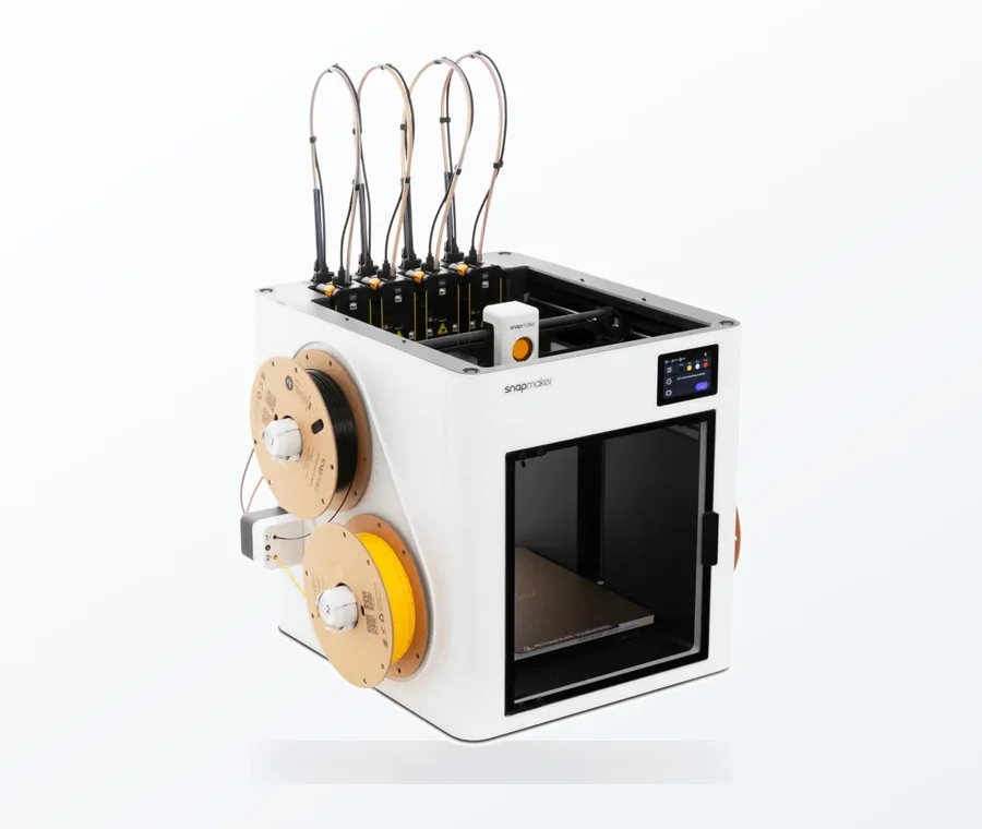
The consumer toolchanger 3D printer: the SnapSwap 4-toolhead system swaps heads in 5 seconds for true multi-color and multi-material printing, with smart calibration and auto filament loading.
- 4 toolheads · 5 s swap
- Up to 500 mm/s · 20,000 mm/s²
- 270 mm cube build volume
- Multi-color & multi-material
BLTouch and CR Touch setup in eight steps
- Power off and unplug the printer.
- Fit the bracket and probe. The probe must be vertical and the retracted pin 2.3–4.3 mm above the nozzle tip.
- Connect the leads and unplug the old Z endstop switch if the probe takes over Z homing.
- Flash firmware with the probe enabled (Creality’s CR Touch firmware, or your own Marlin or Klipper configuration).
- Test deploy, retract and trigger by hand before the probe goes anywhere near the bed.
- Measure and enter the X/Y probe offsets.
- Set the Z-offset with the paper test, save, and run a bed mesh.
- Print a first-layer test and adjust the Z-offset in small steps until the layer is right.
What you need before you start
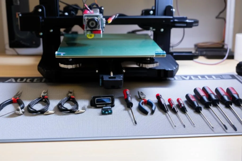
- A mounting bracket for your hotend. Creality’s CR Touch kit includes brackets for the Ender-3, Ender-3 Pro, Ender-3S, Ender-5 family, CR-10, Ender-3 Max and Ender-3 V2, plus M3×8 and M3×6 screws.
- Your board’s pinout. Newer 32-bit boards usually have a labelled 5-pin probe header. Older boards may need a servo pin, soldering or a firmware change; ANTCLABS publishes wiring guides for boards with and without a servo pin.
- The right firmware. Creality lists separate CR Touch firmware files per printer and per board revision (for example 4.2.2 or 4.2.7, with or without a filament sensor). For Marlin you compile your own; for Klipper you edit
printer.cfg. - An SD card, hex keys, a ruler or calipers, and a sheet of ordinary printer paper for the Z-offset.
Mounting height and wiring
ANTCLABS’ drawing for the BLTouch Smart V3.1 puts the tip of the retracted pin 2.3–4.3 mm above the nozzle tip. Too low and the pin drags on the print; too high and the pin may not reach the bed before the nozzle does. The probe also has to stand vertical, and the mount must not flex. For a CR Touch, use Creality’s bracket for your model, which sets the height for you.
| BLTouch lead | Function | Connects to |
|---|---|---|
| Brown (3-pin plug) | GND | Ground on the servo/probe header |
| Red (3-pin plug) | +5 V supply | 5 V on the servo/probe header |
| Orange (3-pin plug) | Control signal (servo PWM) | Servo or probe control pin |
| Black (2-pin plug) | GND | Z-min ground |
| White (2-pin plug) | Z-min trigger signal | Z-min signal pin |
ANTCLABS lists a 4.8–5.1 V supply and warns that reversed polarity can destroy the electronics. The Marlin configuration notes add a practical tip: if the probe deploys but the trigger is never seen, the black and white wires are often swapped, and unlike a mechanical switch they are not interchangeable. On a Creality 32-bit board the CR Touch cable goes into the 5-pin port; Creality’s manual tells you to unplug the Z endstop cable at the same time.
Leave the logic voltage alone unless you have a reason. The V3.1 ships in open-drain (“logic voltage free”) mode, which works on both 3.3 V and 5 V boards. 5 V mode is only for boards with a problematic Z-min input circuit, such as a large capacitor on the endstop line. Both ANTCLABS and Marlin warn that 5 V mode on a 3.3 V board can damage it.
Firmware settings for Marlin and Klipper
If you use Creality’s pre-built CR Touch firmware, flash it from a freshly formatted SD card; Creality’s manual says the update takes about 10 seconds and that you should restore factory settings afterwards. If you build Marlin yourself (see flashing Marlin firmware), these are the options that matter:
| Marlin option | What it does | Value |
|---|---|---|
BLTOUCH | Enables BLTouch and compatible probes | Enabled |
Z_MIN_PROBE_USES_Z_MIN_ENDSTOP_PIN | Probe on the Z-min pin replaces the Z endstop for homing | Enabled if wired to Z-min |
NOZZLE_TO_PROBE_OFFSET | X, Y, Z distance from nozzle to probe trigger point | Measured on your printer |
Z_SAFE_HOMING | Moves the probe to a set XY point (bed centre by default) before homing Z, so it never homes off the bed | Enabled |
AUTO_BED_LEVELING_BILINEAR | Probes a grid and interpolates between points | GRID_MAX_POINTS_X defaults to 3 (3×3) |
EEPROM_SETTINGS | Lets M500 store offsets and mesh | Enabled |
BLTOUCH_SET_5V_MODE | Switches V3.x probes to 5 V output | Only on 5 V-tolerant boards |
Z_MIN_PROBE_REPEATABILITY_TEST | Adds M48 to measure probe repeatability | Worth enabling |
For Klipper, the probe gets a [bltouch] section, Z homing points at the probe, and [safe_z_home] keeps homing on the bed. Your pins depend on the board; the ones below are the example from the Klipper documentation:
[bltouch]
sensor_pin: ^P1.24     # white wire, with pull-up
control_pin: P1.26     # yellow/orange wire

[stepper_z]
endstop_pin: probe:z_virtual_endstop
# remove position_endstop

[safe_z_home]
home_xy_position: 100, 100
z_hop: 10
Already thinking about switching firmware? Our guide to migrating from Marlin to Klipper covers the rest of printer.cfg.
Test the probe before it touches the bed
A probe that never triggers will drive the nozzle into the bed, so check it by hand first.
- Marlin:
M280 P0 S10deploys the pin,M280 P0 S90stows it,M280 P0 S120runs the self-test andM280 P0 S160clears an alarm. With the pin down, push it up with a fingernail and sendM119: the Z probe should change from open to triggered. - Klipper:
BLTOUCH_DEBUG COMMAND=pin_downandpin_uptest the control wire. Then sendpin_down,touch_modeandQUERY_PROBE(should say “open”), push the pin and query again (should say “TRIGGERED”). - First real probe: run
G28with a finger ready to tap the pin, or your hand on the power switch.
Setting the X/Y probe offsets
Marlin’s M851 documentation says to measure from the nozzle tip to the centre of the probe pin with calipers or a ruler. With the usual orientation, a probe to the right of the nozzle has a positive X offset and one to the left a negative one; a probe behind the nozzle has a positive Y offset and one in front a negative one. Getting the Y sign backwards is a common mistake, and it shifts the whole mesh.
Klipper’s method is more precise: put a piece of tape on the bed, run PROBE, mark where the pin touched, and record the position with GET_POSITION. Jog the nozzle exactly over the mark and record that position too. Then x_offset = nozzle X − probe X, and the same for Y.
Z-offset calibration: paper test, then a test print
- Home the printer (Auto Home or
G28). With Z safe homing the probe touches down in the middle of the bed. - Lower the nozzle onto paper. Creality’s method: Prepare → Move Axis → Move Z, and stop when the gap between nozzle and bed is about 0.1 mm, the thickness of a sheet of A4 paper. The Z value on screen is your Z-offset.
- Enter and store it. On Creality screens, enter the value under Z-offset or Probe Z Offset and choose Store Settings. In Marlin, send it as
M851 Z-x.xxfollowed byM500. If your LCD has Marlin’s Probe Offset Wizard, it walks you through the same steps. - In Klipper, run
PROBE_CALIBRATE. It probes automatically, then lets you lower the nozzle to the paper withTESTZ. Finish withACCEPTandSAVE_CONFIG. - Print a first-layer test and adjust live. Lines that are round and barely stick: nozzle too high, so move it down. Lines that are transparent, rough or ploughed: nozzle too low, so move it up. Start with steps of about 0.02 mm and save again when it looks right. This step size is a starting point, not a published value.
Signs differ between firmwares. Marlin stores the Z offset as a negative number for probes that trigger below the nozzle, so “more negative” moves the nozzle closer to the bed. Klipper stores a positive z_offset, and its BL-Touch page says a value close to 1 mm is normal. For a closer look at reading the first layer, see how to dial in your Z-offset.
Creating and loading the bed mesh
- Marlin:
G28, thenG29, thenM500.G28turns leveling off by default, so the start G-code needsG28followed byM420 S1. Marlin’s docs suggest this in place ofG29to save time and machine wear. Creality’s manual takes the other route and changes the slicer’sG28toG28 G29, which probes before every print. - Klipper:
BED_MESH_CALIBRATE, thenBED_MESH_PROFILE SAVE=defaultandSAVE_CONFIG. AddBED_MESH_PROFILE LOAD=defaultto your start macro. Withadaptive_marginset, Klipper probes only the area under the current print; don’t save and reuse those meshes. - Temperature: Klipper notes that many probes read differently at different temperatures and recommends always probing either cold or after the printer has stabilised at print temperature. Creality’s manual recommends leveling with the bed cool. Whichever you choose, do it the same way every time.
- Check repeatability: Klipper’s
PROBE_ACCURACYprobes ten times. A spread of up to about 0.005 mm is normal; more than 0.025 mm means the probe is not accurate enough for bed meshing. Marlin’s equivalent isM48.
BLTouch troubleshooting table
| Symptom | Likely cause | Fix |
|---|---|---|
| Red LED flashing, pin stays up | Alarm state after a failed deploy, or a 5 V/GND wiring fault | Clear the alarm (M280 P0 S160 or BLTOUCH_DEBUG COMMAND=reset); check brown and red wires |
| Pin will not deploy at all | Control wire on the wrong pin, or the core sits too low | Check brown/red/orange wiring; ANTCLABS says to turn the core up to 180° with a hex key so it sits further inside the case |
| Pin deploys but the nozzle crashes | Trigger never reaches the board: black/white swapped, wrong pin or no pull-up | Swap black/white, check the Z-min pin and pull-up; test with M119 or QUERY_PROBE |
| Misses triggers on some Melzi, Anet or Creality boards | Large capacitor on the endstop input | ANTCLABS suggests removing the capacitor, or 5 V mode on 5 V boards only |
| Mesh looks noisy or inconsistent | Loose mount, electrical noise, different probing temperatures | Tighten the bracket, use shielded or twisted cable, probe at a consistent temperature; check PROBE_ACCURACY |
| Probing hits the bed clips or edge | Mesh limits or offsets wrong | Recheck the X/Y offset signs; in Klipper, mesh_min/mesh_max are probe coordinates, not nozzle coordinates |
Common mistakes and next steps
- Expecting the probe to fix a badly tilted bed. A mesh compensates for an uneven surface, but you get better results if the bed is roughly trammed first. Our manual bed leveling guide covers the mechanical part.
- Forgetting to load the mesh. After
G28Marlin prints without compensation unlessM420 S1orG29follows. - Not saving. Offsets set on the screen are lost at power-off without Store Settings,
M500orSAVE_CONFIG. - Old Z-offset after new firmware. Creality recommends restoring factory settings after the update. If leveling then fails, reset the Z-offset to 0 and start again, otherwise the nozzle can hit the bed.
- Blaming the probe for every first-layer problem. A dirty sheet, wrong bed temperature or under-extrusion look similar. Work through first layer adhesion before changing the probe setup.
Frequently asked questions
Do I need new firmware for a BLTouch or CR Touch?
Yes, the firmware has to know the probe is there and how to deploy it. Creality publishes ready-made CR Touch firmware for each supported printer and board revision. For other printers you enable the probe in Marlin and compile, or add a bltouch section in Klipper.
Can I keep the Z endstop switch connected?
If the probe handles Z homing, no. Creality’s manual says to unplug the Z endstop cable when fitting the CR Touch, and in Marlin a probe on the Z-min pin replaces the endstop. Leaving the switch in the circuit can stop Z homing from working properly.
What Z-offset should a BLTouch have?
There is no universal number because it depends on how high the probe is mounted. Marlin usually shows a negative value for probes that trigger below the nozzle, while Klipper stores a positive value and describes about 1 mm as typical. Set it with the paper test and confirm it with a first-layer print.
Do I have to run G29 before every print?
No. Once a mesh is saved with M500, M420 S1 after G28 loads it, which Marlin recommends to save time. Probing every print with G29 still works and catches changes, such as a sheet that sits differently, but adds probing time to every job.