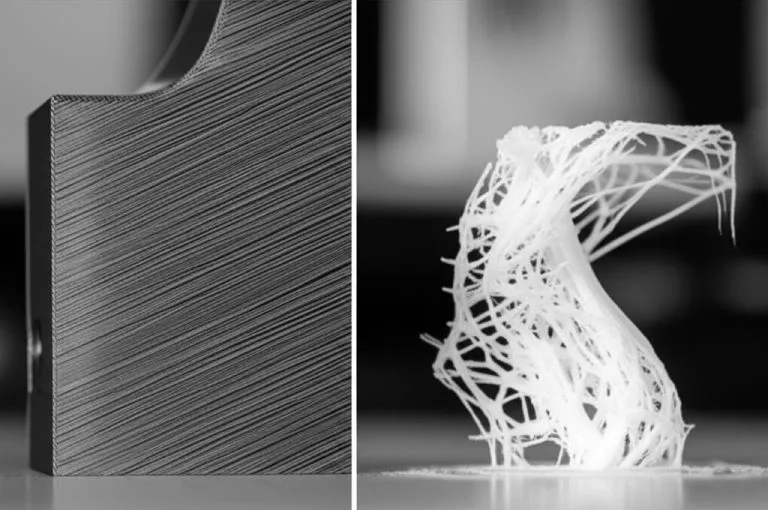
Print speed rarely ruins a surface on its own. The defects come from speed pushing past one of three limits: how much plastic the hotend can melt per second (maximum volumetric speed), how hard the toolhead accelerates into corners (ringing), and speeds at which the motors resonate (fine vertical ripples). Find those limits with calibration prints, then run the outer wall and top surface slower and let hidden infill run fast.
The numbers add up quickly. At a 0.2 mm layer height and 0.45 mm line width, 200 mm/s needs 18 mm³/s of molten filament and 300 mm/s needs 27 mm³/s. Bambu Lab specifies 25 mm³/s for PLA Basic on its H2S, so the slicer would slow the faster setting down to stay under the limit. This guide covers the calibration order, how to read each test, and a table of speed-related defects. Values come from Bambu Lab, OrcaSlicer and Klipper documentation linked at the end.
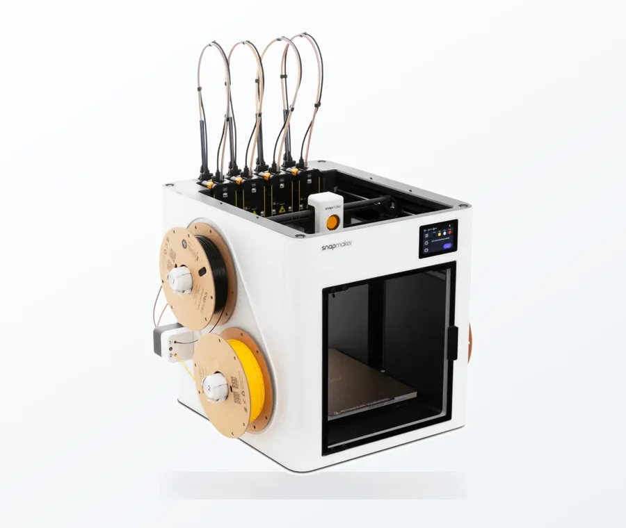
The consumer toolchanger 3D printer: the SnapSwap 4-toolhead system swaps heads in 5 seconds for true multi-color and multi-material printing, with smart calibration and auto filament loading.
- 4 toolheads · 5 s swap
- Up to 500 mm/s · 20,000 mm/s²
- 270 mm cube build volume
- Multi-color & multi-material
Print speed calibration in eight steps
- Fix the mechanics first: belt tension, frame rigidity, loose parts.
- Dial in nozzle temperature for the filament.
- Run a max volumetric speed test and set the limit 10–20% below the result.
- Tune pressure advance (linear advance), if your firmware supports it.
- Calibrate flow.
- Print a ringing test, tune input shaping and choose a maximum acceleration.
- Print a speed test tower and pick an outer wall speed that avoids resonance bands.
- Print a real part with the new profile and compare it with the old one.
This follows OrcaSlicer’s recommended calibration order (temperature, max volumetric speed, pressure advance, flow, retraction, cornering, input shaping, VFA, tolerance), leaving out the steps that don’t bear on surface finish.
Which slicer speed settings affect surface finish
A single global speed is a blunt tool. Slicers split speed by feature, so you can slow down only what people see:
| Setting | Visible on the part? | How to set it |
|---|---|---|
| Outer wall speed | Yes, every side wall | Slower than inner walls; OrcaSlicer describes it as usually slower for quality and layer adhesion |
| Outer wall acceleration | Yes, corners and edges | Lower than general printing acceleration |
| Top surface speed and acceleration | Yes, flat tops | Similar to the outer wall, per OrcaSlicer |
| Small perimeters | Yes, small holes and details | Its own speed for tiny outlines; lower it if small features look rough |
| Inner wall speed | No | Faster than the outer wall, but still below the maximum volumetric speed |
| Sparse infill speed | No | Faster than solid infill to save time |
| Travel acceleration | No | Usually higher than printing moves to cut travel time |
The relative guidance comes from OrcaSlicer’s acceleration and speed documentation. It doesn’t give universal numbers, because the right values depend on your printer and hotend; the tests below give you those.
Max volumetric speed: the real speed limit
Bambu Lab’s formula ties toolhead speed to how much filament the hotend has to melt:
Volumetric speed (mm³/s) = layer height (mm) × line width (mm) × print speed (mm/s)
| Layer height | Line width | Speed | Volumetric speed |
|---|---|---|---|
| 0.2 mm | 0.45 mm | 100 mm/s | 9 mm³/s (calculated) |
| 0.2 mm | 0.45 mm | 200 mm/s | 18 mm³/s |
| 0.2 mm | 0.45 mm | 300 mm/s | 27 mm³/s |
| 0.16 mm | 0.45 mm | 250 mm/s | 18 mm³/s |
| 0.3 mm | 0.45 mm | 250 mm/s | 33.8 mm³/s |
When a slicer knows the filament’s maximum volumetric speed, it automatically lowers speed wherever a toolpath would exceed it. If that limit is set too high, Bambu Lab lists what you will see:
- Thin walls and poor accuracy: a 0.45 mm wall might come out at 0.35 mm or less, and small holes may close up.
- Under-extrusion gaps in walls and rough infill.
- Weak overhangs and sagging bridges.
- Shine or gloss variation when volumetric speed changes rapidly.
- Weak layer bonding that can lead to cracks or fragile parts, plus a higher risk of clogs and extruder gear wear.
Running the max volumetric speed test
OrcaSlicer’s built-in test prints a tower that steps up the flow as it grows. The suggested defaults are 5 to 20 mm³/s in 0.5 mm³/s steps. Measure the height where defects start and calculate: max volumetric speed = start + (measured height × step). At 19 mm with the defaults that is 5 + (19 × 0.5) = 14.5 mm³/s. OrcaSlicer suggests reducing the result by 10–20%, or more, to protect print quality and strength.
If the limit holds you back, Bambu Lab suggests three ways to gain headroom: lower the layer height, raise the nozzle temperature by 5–10 °C (a last resort, since it can add stringing and drooping overhangs), or fit a larger nozzle at the cost of fine detail. As an example, it quotes about 35 mm³/s with PLA Basic on an H2-series 0.4 mm High Flow nozzle and up to 40 mm³/s with the 0.6 mm version. For hardware options, see upgrading your hotend for volumetric flow.
Ringing, acceleration and input shaping
Ringing (also called ghosting or echoing) repeats edges and lettering as faint echoes along the wall. Klipper’s documentation explains that it comes from mechanical vibrations caused by quick changes of direction, and that it usually has mechanical origins: an insufficiently rigid frame, loose or springy belts, misaligned parts, or heavy moving mass. Check those first; see calibrating belt tension.
Klipper’s ringing test holds speed steady and steps acceleration up, which shows where your printer’s limit really is:
- Slice the ringing tower with outer walls at around 80–100 mm/s, a minimum layer time of 3 seconds or less, and pressure advance disabled.
- Use a tuning tower that raises acceleration from 1,500 mm/s² by 500 mm/s² every 5 mm, up to 7,000 mm/s² in the last band.
- With input shaping enabled, note the highest band where ringing is still acceptable.
- Check the 0.15 mm gap in the test wall. As acceleration rises, input shaping smooths the toolpath and the gap widens. In Klipper’s example it starts to grow at 3,500 mm/s², so 3,000 mm/s² is chosen.
- Set max acceleration to the lower of the two values. Don’t raise square corner velocity above its default of 5 mm/s, as that adds smoothing.
Some printers ship with input shaping in the firmware. Prusa, for example, runs Input Shaper on the CORE One, MK4 and XL families with matching slicer profiles, and still asks you to check belts and smooth rods first. The input shaping calibration guide covers accelerometer-based tuning.
Finding resonance-free outer wall speeds

Some surface ripples have nothing to do with corners. OrcaSlicer calls them vertical fine artifacts (VFA): small imperfections on vertical walls, often caused by motor resonance at particular speeds (motor resonance rippling). Because they depend on speed, printing slower is not automatically smoother.
- In OrcaSlicer, open the VFA speed test and set a range covering every outer wall speed you use, for example 20 to 200 mm/s.
- Choose the step between bands, for example 10 mm/s.
- Print the tower and inspect it under a low, raking light. Note bands that look rougher than their neighbours.
- Set your outer wall speed in a clean band, or enter the rough band in OrcaSlicer’s resonance avoidance speed range.
Other fixes OrcaSlicer lists are input shaping, jerk or junction deviation tuning, and mechanical changes to motors, belts or pulleys.
| What you see | Likely cause | Fix |
|---|---|---|
| Echoes of edges or letters just after corners | Ringing from acceleration and frame or belt vibration | Check belts and frame, lower outer wall acceleration, tune input shaping |
| Fine, even ripples across whole walls, only at some speeds | Motor resonance (VFA) | VFA speed tower; move the outer wall speed out of the bad band |
| Rounded corners; the gap in the ringing test wall widens at high acceleration | Input shaper smoothing | Lower max acceleration; keep square corner velocity at default |
| Bulging corners on the ringing test | Pressure advance disabled or flow too high | Tune pressure advance and flow |
| Gaps in walls, thin walls, rough infill at high speed | Maximum volumetric speed exceeded | Calibrate the limit and set it 10–20% lower |
| Shiny and matte patches on the same wall | Rapid changes in volumetric speed | Check the slicer’s flow preview for spots where speed or flow jumps, and even out the wall speeds |
| Layers split easily, part snaps along a layer | Hotend can’t melt enough filament at that speed | Reduce speed or layer height; small temperature increase as a last resort |
For corner blobs and seam bulges in normal prints, see our guide to pressure advance.
What slowing down won’t fix
Horizontal layer lines on curved or sloped surfaces come mainly from layer height, not speed. Bambu Lab notes that thinner layers reduce visible layer lines and give smoother curves, at the cost of much longer print times. If lines are your main complaint, start with choosing the right layer height and eliminating visible layer lines. A visible seam line is a placement problem rather than a speed one.
Common print speed tuning mistakes
- Turning the global speed down instead of only the outer wall and top surface. You pay the time cost on infill that nobody sees.
- Tuning speed before temperature and flow. A wrong temperature or flow shows up as defects that look like speed problems.
- Using the raw max volumetric speed result with no safety margin.
- Raising square corner velocity or jerk to make corners faster, which adds smoothing or ringing.
- Calibrating a printer with loose belts. Klipper says to fix mechanical causes of ringing first; any tuning done before that has to be redone.
- Keeping one profile for every filament. Bambu Lab points out that PETG, ABS and TPU have lower maximum volumetric speeds than PLA, so a PLA-tuned speed can under-extrude them.
Frequently asked questions
What is the best print speed for quality?
There is no single number, because the limit depends on your hotend, filament, layer height and frame. Work out the flow a speed needs (layer height × line width × speed), keep it below your calibrated maximum volumetric speed, and use a speed test tower to pick an outer wall speed that avoids resonance bands.
Does printing slower always improve surface finish?
Not always. Slowing down reduces flow demand and acceleration-related ringing, but some motor resonance ripples appear only at particular speeds, including low ones. A VFA speed tower shows which speeds are clean on your printer.
How do I calculate max volumetric speed?
Multiply layer height by line width by print speed. For example, 0.2 mm × 0.45 mm × 200 mm/s = 18 mm³/s. To find your printer’s limit, print OrcaSlicer’s max volumetric speed test, calculate the result from the height where defects start, and set it 10–20% lower.
Is acceleration or speed more important for ringing?
Ringing comes from vibrations caused by quick changes of direction, so acceleration is the main lever. Klipper’s ringing test keeps speed at around 80–100 mm/s and increases acceleration in steps to find the limit. Loose belts and a flexible frame make it worse at any setting.