In the intricate world of 3D printing, achieving flawless output is often a quest marked by meticulous calibration and continuous refinement. Among the most common and frustrating visual imperfections that can plague even well-tuned machines are ‘ghosting’ and ‘ringing.’ These unsightly print artifacts, manifesting as faint ripples or echoes of features on a printed surface, can dramatically detract from the quality and aesthetic appeal of your creations. Fortunately, advanced calibration techniques, particularly input shaping, offer a powerful solution to banish these issues and unlock your printer’s full potential for speed and precision.
Understanding print artifacts: ghosting and ringing
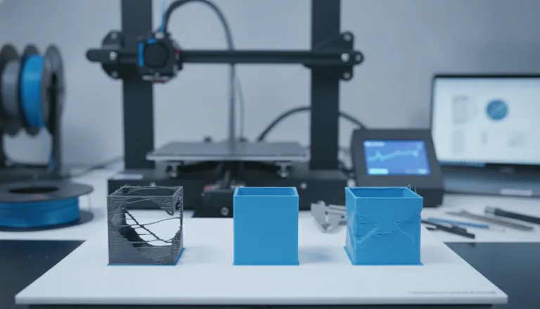
Before diving into the solution, it’s crucial to understand the problem. Ghosting, often called ‘salmon skin’ or ‘echoing,’ refers to faint, repeated patterns that appear adjacent to sharp corners or features on a print. Imagine printing a cube with a prominent letter ‘A’ on its side; ghosting would appear as a faint ‘A’ repeating slightly to the left or right of the main feature. Ringing, on the other hand, typically presents as visible waves or ripples that extend outwards from features like corners or holes, resembling the concentric circles formed when a pebble drops into water.
The root cause: mechanical resonance
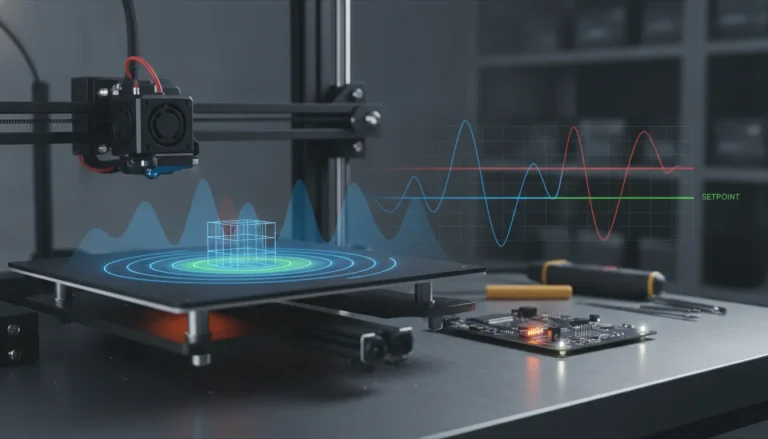
Both ghosting and ringing are direct consequences of mechanical resonance within your 3D printer. When a printer’s printhead (or bed, in some configurations) rapidly changes direction, especially at high speeds and accelerations, it imparts forces onto the printer’s frame, belts, and other moving components. These forces can excite natural frequencies within the mechanical system, causing vibrations that persist for a short period after the initial movement. As the nozzle continues to lay down plastic while these vibrations are still occurring, the molten filament is deposited slightly off its intended path, resulting in the tell-tale ripples or echoes.
- Factors contributing to resonance:
- Printer frame: A less rigid frame is more susceptible to vibrations.
- Moving mass: Heavier printheads or beds have more inertia, leading to greater forces during direction changes.
- Belt tension: Loose or unevenly tensioned belts can exacerbate oscillations.
- Stepper motors: The inherent step-by-step motion of stepper motors can induce micro-vibrations.
The science behind input shaping
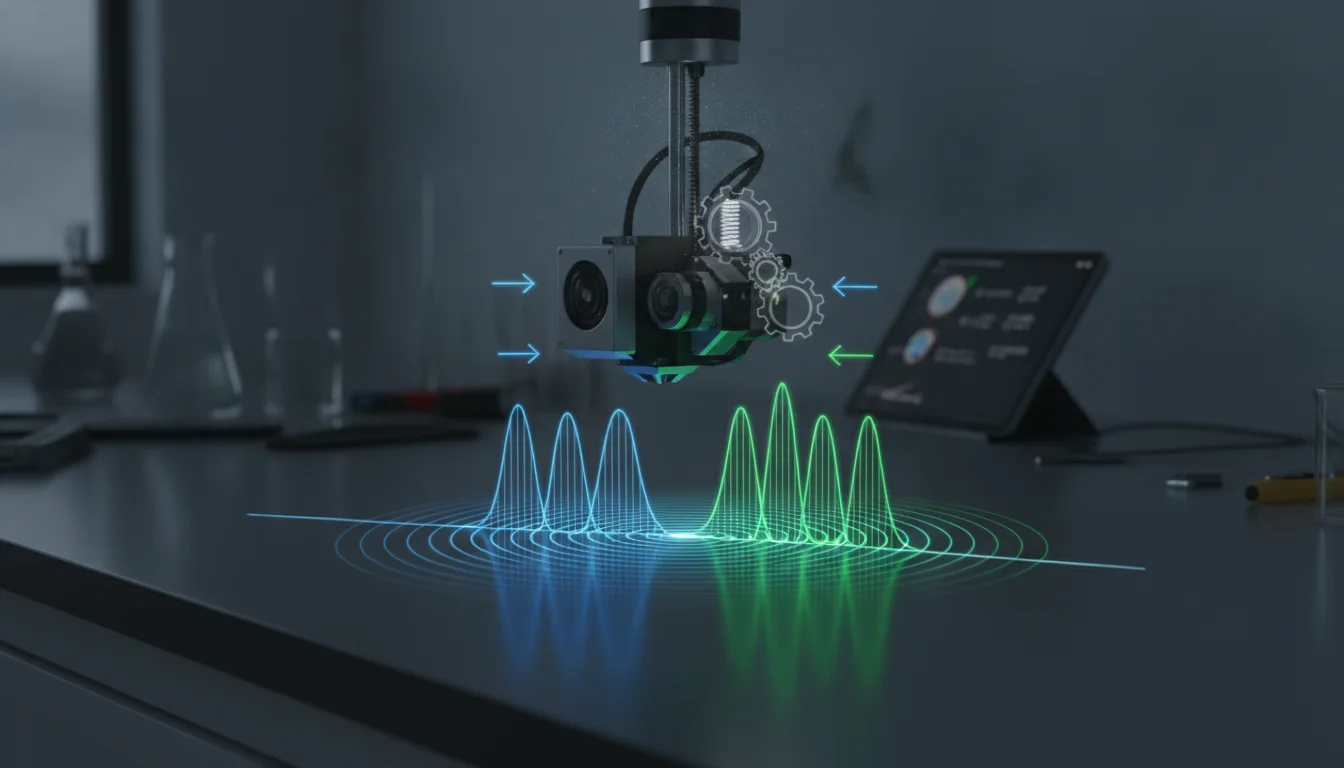
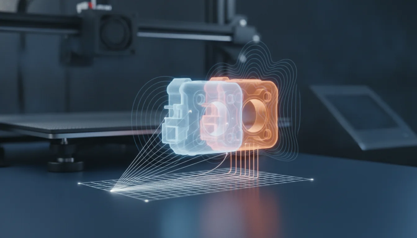
Input shaping is a control technique designed to reduce or eliminate residual vibrations in mechanical systems. Its core principle is elegant: instead of trying to damp vibrations after they occur, input shaping modifies the command signal to the motors before the motion begins. By adding precisely timed, small impulses to the original motion command, it effectively cancels out the natural resonant frequencies of the system. Think of it like throwing a second, perfectly timed stone into the water to cancel out the ripples from the first.
How input shaping works in 3D printing
In the context of 3D printing, input shaping algorithms analyze the printer’s resonant frequencies (typically for the X and Y axes) and then generate a modified motion profile. When the printhead is commanded to move, the input shaper applies a series of micro-accelerations and decelerations that, when combined with the printer’s natural response, result in a smoother, vibration-free motion. This allows for faster accelerations and higher print speeds without introducing ghosting or ringing.
There are various types of input shapers, each with different characteristics regarding vibration suppression, robustness to frequency variations, and added move time. Common types you might encounter include Zero Vibration (ZV), Zero Vibration and Derivative (ZVD), Extra-Insensitive (EI), and Modified Zero Vibration (MZV). The choice of shaper type and its corresponding frequency is critical for optimal performance.
Implementing input shaping: Klipper vs. Marlin
While the concept of input shaping is universal, its implementation and calibration process differ significantly depending on your printer’s firmware. The two dominant players in this arena are Klipper and, more recently, Marlin.
Klipper’s advanced approach to input shaping
Klipper has long been at the forefront of advanced 3D printer control, and its input shaping implementation is a prime example. Klipper leverages a separate, more powerful host computer (like a Raspberry Pi) to offload complex calculations from the printer’s limited mainboard. This architectural advantage allows for sophisticated algorithms and real-time processing, making Klipper an ideal platform for precise input shaping.
Accelerometer-based calibration with Klipper
The gold standard for input shaping calibration in Klipper involves using an accelerometer, typically an ADXL345. This tiny sensor is temporarily mounted onto the printhead (and sometimes the bed) to directly measure the printer’s actual vibrations across its X and Y axes. The process generally involves:
- Hardware setup: Wiring the ADXL345 to the Raspberry Pi or a separate microcontroller.
- Software configuration: Enabling the accelerometer in Klipper’s printer.cfg file.
- Vibration measurement: Klipper runs a series of specific test movements, and the accelerometer records the resonance frequencies and their amplitudes for each axis.
- Automated calculation: Klipper analyzes the collected data and recommends the optimal input shaper type and frequency for each axis.
- Application: The recommended settings are then added to the printer.cfg, typically under [input_shaper].
Benefits of accelerometer-based calibration:
- High precision: Directly measures actual printer resonances, leading to highly accurate compensation.
- Objectivity: Eliminates subjective visual interpretation of test prints.
- Efficiency: The process is relatively quick and automated once set up.
- Optimization: Can identify multiple resonant frequencies and apply complex shapers for superior results.
Manual (test print) calibration with Klipper
While less precise than accelerometer-based methods, Klipper also supports a manual calibration approach using test prints. This involves printing a series of specially designed test patterns (often tall towers with sharp corners) at various input shaper frequencies and types. The user then visually inspects the prints to determine which settings yield the best results. This method is more time-consuming and relies on subjective judgment but can still provide significant improvements if an accelerometer isn’t available.
Marlin’s resonance compensation
Marlin, the venerable workhorse of 3D printer firmware, has also integrated its own form of resonance compensation, often referred to as ‘Input Shaping’ or ‘Linear Advance’ (though Linear Advance is a different feature, some confusion can arise). While Marlin’s implementation may not offer the same level of granular control or the automated, accelerometer-driven precision as Klipper, it can still provide notable improvements to print quality.
Enabling and configuring in Marlin
Enabling resonance compensation in Marlin typically requires recompiling the firmware. Users need to enable specific options in Configuration_adv.h, such as #define INPUT_SHAPING_X and #define INPUT_SHAPING_Y. Calibration often relies on a manual process similar to Klipper’s test print method:
- Firmware compilation: Enable input shaping features and compile Marlin.
- Test prints: Print specific patterns designed to highlight ghosting and ringing.
- G-code commands: Use M-codes (e.g., M593) to set input shaper types and frequencies, adjusting them iteratively based on visual inspection of test prints.
- Saving settings: Once optimal settings are found, they can be saved to EEPROM or integrated into the firmware for future use.
Comparing Klipper and Marlin for input shaping
When considering Klipper versus Marlin for input shaping, several factors come into play:
- Precision and automation: Klipper, with its accelerometer integration, offers a significantly more precise and automated calibration process. Marlin’s manual approach is more susceptible to human error and less capable of identifying complex resonant profiles.
- Ease of use (calibration): Once the initial Klipper setup is done, accelerometer calibration is straightforward. Marlin’s iterative test print approach can be more time-consuming and require more subjective judgment.
- Hardware requirements: Klipper requires a separate host computer (e.g., Raspberry Pi) and an optional accelerometer. Marlin runs directly on the printer’s mainboard, but advanced features might push the limits of less powerful 8-bit boards.
- Flexibility and tuning: Klipper allows for real-time adjustment of parameters and has a more extensive range of shaper types and configurations. Marlin’s options are generally more limited and require firmware recompilation for significant changes.
- Community and development: Both have active communities, but Klipper’s development in input shaping has been particularly rapid and feature-rich.
For those seeking the highest level of print quality, speed, and precision through input shaping, Klipper typically presents a more robust and sophisticated solution, especially when coupled with an accelerometer. Marlin offers a more integrated, albeit often less precise, approach that can be suitable for users who prefer to stick with a single firmware ecosystem and are comfortable with manual tuning.
The calibration process: a step-by-step guide (Klipper-focused)
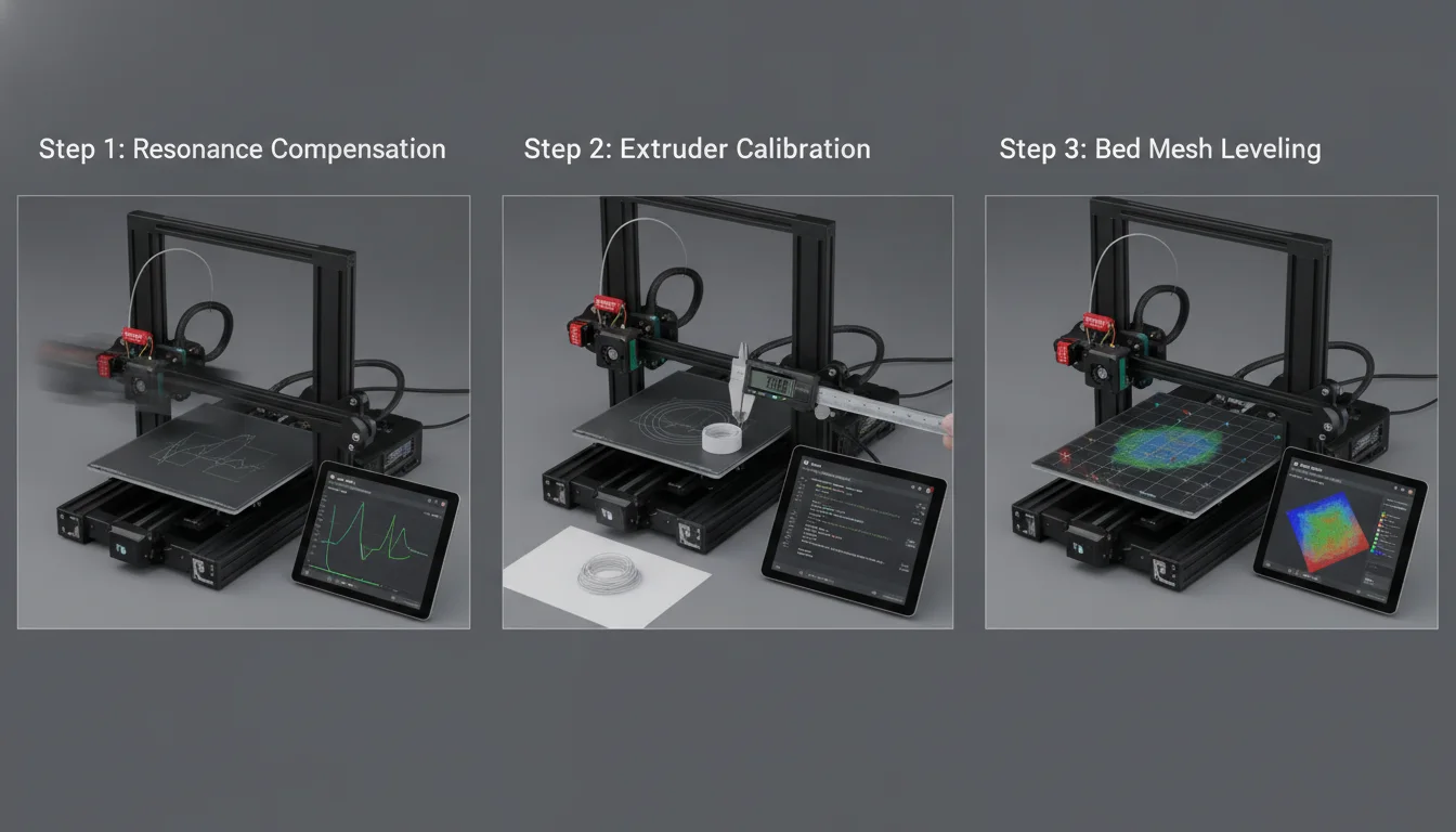
Given its prominence in input shaping, we’ll outline a general calibration process primarily for Klipper, focusing on the accelerometer method. The principles, however, can be adapted for manual calibration across both firmware types.
Prerequisites for successful calibration
Before you even think about input shaping, ensure your printer is in tip-top mechanical condition. Input shaping compensates for resonances, it doesn’t fix underlying mechanical issues.
- Sturdy frame: Ensure all bolts are tightened, and your printer isn’t wobbly.
- Belt tension: Belts should be adequately tensioned – not too loose to skip, not too tight to strain motors or bearings. Even tension across both axes is crucial.
- Smooth motion: Rails and linear guides should be clean, well-lubricated, and free of binding.
- Nozzle and bed leveling: While not directly related to resonance, a well-calibrated printer is essential for evaluating print quality post-shaping.
Klipper accelerometer calibration walkthrough
This process assumes you have Klipper installed and configured on your printer.
1. Mount the accelerometer
Securely mount the ADXL345 to your printhead. It needs to be rigid and unable to move independently of the printhead. Some users design custom mounts that attach to the hotend shroud or printhead carriage. Ensure the orientation is correct, typically with the arrow on the ADXL345 PCB pointing towards the front of the printer.
2. Wire the accelerometer
Connect the ADXL345 to your Raspberry Pi (or other Klipper host). Standard connections involve VCC, GND, SCL, SDA (for I2C) or MOSI, MISO, SCK, CS (for SPI). Refer to Klipper’s official documentation for specific wiring diagrams for your host device.
3. Configure Klipper for the accelerometer
Edit your printer.cfg file via SSH or your web interface (Fluidd/Mainsail). Add a section for the accelerometer, specifying its address and pins. For example:
[adxl345]
cs_pin: rpi:gpiochip0/gpio8 # Example for Raspberry Pi SPI
spi_bus: spi0a
axes_map: x,y,z # Verify your accelerometer orientation
[resonance_tester]
accel_chip: adxl345
probe_points: 100,100,20 # Adjust to a safe point near the center of your bed
Restart Klipper after making changes.
4. Run the calibration commands
Open the console in Fluidd or Mainsail and execute the following commands:
- TEST_RESONANCES AXIS=X
- TEST_RESONANCES AXIS=Y
Klipper will move your printhead rapidly across the specified axis, measuring vibrations. This process can take several minutes per axis. You might hear strange noises; this is normal.
5. Analyze results and apply settings
After the tests, Klipper will output recommendations for the optimal input shaper type and frequency for each axis. For instance, it might suggest MZV at 50Hz for X and EI at 45Hz for Y.
Add these settings to your printer.cfg under the [input_shaper] section:
[input_shaper]
shaper_type_x = mzv
shaper_freq_x = 50.0
shaper_type_y = ei
shaper_freq_y = 45.0
Save and restart Klipper. Your input shaping is now active!
Manual (test print) calibration method
If you’re using Marlin or don’t have an accelerometer for Klipper, you’ll rely on test prints. This involves:
- Prepare test models: Use models specifically designed to show ghosting/ringing, such as a tall, thin tower with sharp corners or a hollow cube with features on its faces.
- Baseline print: Print the model without any input shaping enabled to establish a baseline for comparison.
- Iterative testing:
- Start with a default shaper type (e.g., ZV or MZV) and a reasonable frequency range (e.g., 30-70Hz).
- Print multiple models, changing the shaper frequency for each (e.g., M593 X F50 for 50Hz on X axis in Marlin).
- Visually inspect each print to find the frequency that minimizes ghosting/ringing.
- Repeat the process for the Y axis.
- Experiment with different shaper types if initial results aren’t satisfactory.
- Apply settings: Once optimal settings are found, configure them in your firmware (Marlin) or printer.cfg (Klipper).
Fine-tuning and troubleshooting
Every model we design and test gets uploaded as a free STL – browse the full profile on MakerWorld.
Input shaping is powerful, but it’s not a set-it-and-forget-it solution. Fine-tuning can yield even better results, and knowing how to troubleshoot is essential.
Impact of different shaper types
Different shaper types offer various trade-offs:
- ZV (Zero Vibration): Simple, effective for a single frequency, but less robust to frequency changes.
- MZV (Modified Zero Vibration): More robust than ZV, often a good general-purpose choice.
- EI (Extra-Insensitive): Highly robust to frequency variations, good for printers with less stable resonances, but can add slightly more printing time.
- ZVDD (Zero Vibration, Derivative, Double Derivative): Offers very strong vibration suppression but can also add more printing time.
Klipper’s accelerometer calibration usually recommends the best shaper, but manual experimentation can sometimes refine it.
Adjusting acceleration and deceleration settings
Input shaping allows for higher print speeds and accelerations. After calibrating input shaping, you might be able to increase your max_accel and max_accel_to_decel settings in your printer’s configuration. Start with conservative increases and test prints to ensure quality isn’t compromised. The goal is to find the sweet spot where you maximize speed without reintroducing artifacts.
Common issues and solutions
- New artifacts appear: If new, strange patterns appear, your input shaper frequency might be off, or you might be over-shaping. Re-run calibration or adjust frequencies slightly. Ensure your mechanical setup is sound.
- Ghosting/ringing persists: If artifacts remain, your shaper frequency might still be incorrect, or the shaper type isn’t ideal. Consider re-running accelerometer calibration if possible, or try different shaper types and frequencies with test prints. Check for mechanical looseness or excessive belt tension.
- Print time increases dramatically: Some shaper types (like EI or ZVDD) can add a small amount of print time due to their more complex impulse sequences. This is usually a worthwhile trade-off for quality, but if the increase is excessive, consider a simpler shaper type.
When to re-calibrate
Re-calibration is recommended after:
- Significant printer modifications: Any changes to moving mass (e.g., new hotend, printhead, bed), frame rigidity, or belt systems.
- Changes in environment: While less common, extreme temperature or humidity shifts could subtly affect materials.
- Firmware updates: Especially if the input shaping algorithms have been updated.
- Noticeable degradation in print quality: If ghosting or ringing starts to reappear.
Benefits beyond print quality

The primary goal of input shaping is to eliminate print artifacts, but its advantages extend further:
- Higher print speeds: By mitigating vibrations, printers can achieve significantly faster acceleration and print speeds without compromising surface quality. This translates to reduced print times and increased throughput.
- Reduced wear and tear: Less vibration means less stress on motors, belts, bearings, and the printer frame, potentially extending the lifespan of components.
- Quieter operation: A printer with effectively tuned input shaping will often run quieter, as it’s not constantly vibrating at its resonant frequencies.
Conclusion
Input shaping stands as a cornerstone of advanced 3D printer calibration, offering a robust and scientifically grounded method to combat the perennial problems of ghosting and ringing. Whether you opt for the precision of Klipper’s accelerometer-driven calibration or the more hands-on approach of Marlin’s manual tuning, embracing input shaping will undoubtedly elevate your 3D printing experience. By understanding the underlying principles and diligently following the calibration steps, you can unlock unparalleled print quality and speed, transforming your printer from a source of frustration into a reliable workhorse capable of producing truly pristine parts. Dive in, experiment, and prepare to be amazed by the difference it makes!
Frequently asked questions
Do I need an accelerometer to use input shaping?
No, but it makes calibration significantly easier and more precise. Klipper supports a manual test print method where you print patterns at different shaper frequencies and visually select the best result. Marlin’s input shaping also relies on this manual, test-print approach by default. However, Klipper’s accelerometer-based calibration directly measures your printer’s actual resonances, removing guesswork and typically yielding superior results.
Will input shaping fix ghosting caused by loose belts or a wobbly frame?
No. Input shaping compensates for mechanical resonance, but it cannot fix underlying mechanical problems. Loose belts, a wobbly frame, or binding rails will still cause print defects. The article stresses that before calibrating input shaping, you must ensure your printer is in tip-top mechanical condition: all bolts tightened, belts properly tensioned, and motion axes smooth. Fix those issues first, then apply input shaping.
Can I enable input shaping on an 8-bit mainboard running Marlin?
Possibly, but with limitations. Marlin’s input shaping runs directly on the printer’s mainboard, and the article notes that advanced features might push the limits of less powerful 8-bit boards. While you can enable it in firmware, the board may struggle with the additional calculations, potentially causing stuttering or missed steps. Klipper offloads these calculations to a separate host computer (like a Raspberry Pi), which is why it is generally preferred for input shaping.