A replacement vacuum cleaner clip is a small latch, hook or snap part that you measure with calipers, model in CAD and print in a plastic that suits the heat and flexing at its location. The short version: measure the part it mates with (not only the broken clip), add roughly 0.15–0.40 mm of clearance depending on the fit, print a small test piece of the interface before the full clip, and pick PETG for a clip that flexes, ASA if it sits near warm air, and PLA only for a rigid part in a cool spot.
The clearance figures below come from a university makerspace guide for Prusa printers, and the material temperatures come from Prusa’s material articles. Both are starting points: printers, filaments and calibration differ. Parts that carry mains voltage, sit against the motor or have a safety function are poor candidates for a home print.
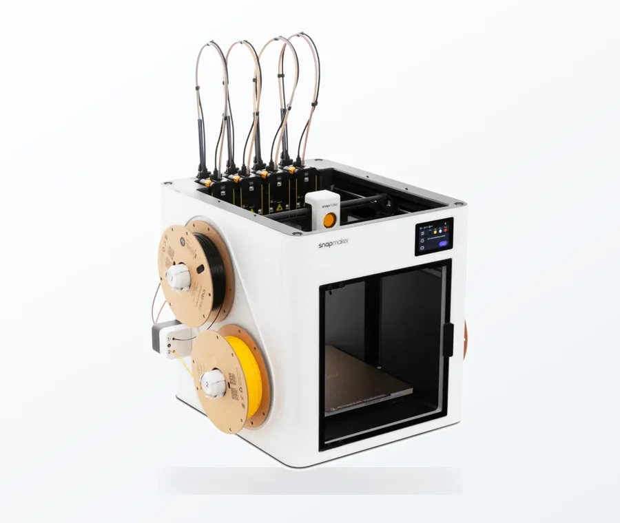
The consumer toolchanger 3D printer: the SnapSwap 4-toolhead system swaps heads in 5 seconds for true multi-color and multi-material printing, with smart calibration and auto filament loading.
- 4 toolheads · 5 s swap
- Up to 500 mm/s · 20,000 mm/s²
- 270 mm cube build volume
- Multi-color & multi-material
Replacement clip in 7 steps
- Identify the part. Note the vacuum’s model number, check whether the maker sells the part, and whether a model of it already exists on a model-sharing site. Printing is the better option when the part is discontinued or sold only inside a larger assembly.
- Keep every fragment and photograph it. Note how the clip moves (snaps, slides or pivots) and exactly where it broke. Breaks show you the stress point.
- Measure the mating features with digital calipers (table below). Write each value down.
- Model the clip in any CAD tool you like: sketch the profile, extrude it to thickness, then add fillets and the hook or latch geometry.
- Apply clearance to every surface that has to slide or snap against another part (clearance table below).
- Print a test piece of just the critical interface, not the whole clip.
- Print the clip, test-fit and adjust. Change one dimension at a time and note what you changed.
What to measure
Measure the slot, hole or rail the clip fits into on the vacuum body as well as the broken clip. The old clip may have worn or been bent before it broke, so it is a reference, not the truth.
| Feature | How to measure | Common trap |
|---|---|---|
| Slot or hook width | Calipers, outside jaws on the clip, inside jaws on the slot | Measuring the clip only; the slot may differ |
| Thickness of the part it snaps over | Calipers at 2–3 points | Moulded parts taper; use the thickest and thinnest values |
| Hole diameter and pin spacing | Inside jaws; measure centre to centre if two pins | Spacing matters more than the hole diameter |
| Hook depth and angle | Photograph beside a ruler, trace it in CAD | A hook that is too shallow slips off |
| Space around the part | Measure with the clip fitted | A clip can fit the slot but hit a neighbouring wall |
Clearance starting points
Printed surfaces never come out exactly at the CAD size, so leave a gap between the faces that have to mate. The University of Florida makerspace guide for the Prusa MK4 and XL gives these rules of thumb:
| Fit | Clearance | Typical use (from the guide) |
|---|---|---|
| Loose | 0.30–0.40 mm | Covers and adjustable parts |
| Standard sliding | 0.20–0.25 mm | Tabs, rails, enclosures |
| Snug / locating | 0.15–0.20 mm | Locating features |
The guide does not say whether the figure is per side or total, and it does not give the nozzle, layer height or material behind it, so treat the values as the range to test. For a snap hook entering a slot, start in the sliding row. Print one strip with the same interface at several clearances (for example 0.15, 0.20, 0.25 and 0.30 mm, labelled), and use the smallest one that goes on with light finger pressure and does not rattle.
Test strip: how to run it
- Copy only the part of the clip that engages the vacuum body: the hook, tab or pin, plus a few millimetres of body. Make 3–4 copies on one plate, each with a different clearance, and engrave or emboss a number on each.
- Print with the same material, nozzle, layer height and orientation you will use for the real clip. A test in PLA tells you little about a PETG clip.
- Try each copy on the vacuum body. Pick the one that engages with light finger pressure, holds when you tug it gently and does not rattle.
- Use that clearance in the full model. If every copy is too tight or too loose, shift the whole range by 0.1 mm and print again.
Which material for a vacuum clip
| Material | Prusa’s figures and notes | Fit for a clip |
|---|---|---|
| PLA | Nozzle 210–215 °C, bed 60 °C. Gets soft and deforms above 60 °C; breaks along layers or into shards on impact | Rigid parts in cool places, not for flexing latches |
| PETG | Nozzle 240 °C, bed 85–90 °C. High tenacity and flexibility; suitable for temperatures below 80 °C | First choice for a clip that bends on and off |
| ASA | Nozzle 260 °C, bed 105–110 °C. UV and temperature resistance up to 93 °C; warps, so use an enclosure and ventilate | Parts near warm air, or in a garden or car vacuum |
Nylon and carbon-filled filaments are an option for high-load clips; the strong filament guide compares them. If the old clip was rubbery, flexible TPU may be the better match, but it needs different settings. For PETG temperatures and bed surface, see the PETG print settings guide.
Walls, orientation and settings
- Wall thickness. Make walls a multiple of the nozzle width. Formlabs gives 1.2 mm for a 0.4 mm nozzle as an example, and lists 1 mm as the FDM minimum for a supported wall. A thin clip is mostly walls, so infill barely matters.
- Starting settings. Three or four perimeters and 30–50% infill are an example starting point, not a tested recipe. Add perimeters before adding infill if it breaks.
- Orientation. Print a flexing arm lying flat so it bends within the layer plane. If the arm stands upright and bends, the stress pulls layers apart. Prusa notes PLA breaks along layers; the print orientation guide explains the rule, and layer adhesion covers weak layers.
- Stress points. Round the inside corner at the root of a flexing arm with a fillet instead of a sharp corner.
Fit problems and fixes
| Symptom | Likely cause | Fix |
|---|---|---|
| Will not seat | Clearance too small, or first-layer edge flared | Add 0.05–0.10 mm, chamfer the bottom edge, retest on the strip |
| Rattles or falls out | Clearance too large, or the original slot is worn | Reduce by 0.05 mm, or add a small bump or detent |
| Snaps when flexed | Layers across the arm, brittle material, sharp corner | Rotate the part, switch to PETG, add a fillet |
| Softens or creeps near heat | PLA close to a warm area | Reprint in PETG or ASA |
| Corners lift (ASA) | Warping | Enclosure and brim; see the warping guide |
Common mistakes
- Copying the broken clip exactly. It broke for a reason. Thicken the root of the flexing arm, add a fillet or change the printing direction instead of reproducing the weak spot.
- Skipping the test strip and printing the full clip at an untested clearance.
- Choosing PLA by default. It is the easiest filament to print, but it softens above 60 °C according to Prusa and it is brittle in thin flexing sections.
- Forgetting the surroundings. A clip that fits its slot can still foul a neighbouring wall, a cable or the filter housing; check the whole assembly before printing.
- Changing several things per reprint. You will not know which change helped.
For other household parts the same method applies; the functional household items guide covers general design rules.
Frequently asked questions
What is the best filament for a vacuum clip that has to flex?
PETG is a good first choice. Prusa describes it as having high tenacity and flexibility, and rates it for temperatures below 80 °C. PLA is brittle and breaks along layers, and TPU only makes sense if the original clip was rubbery.
How do I get the fit right without many reprints?
Measure the part the clip fits into, apply 0.15–0.40 mm of clearance depending on the fit, and print a short strip of the interface at several clearances first. Changing one value per reprint shows which change fixed the problem.
Can I get the clip printed without owning a printer?
Yes. Model it in free CAD, export an STL and send it to a makerspace, library or online print service. Costs vary by service and material, so ask for a quote before ordering.
Is a printed clip safe inside a vacuum cleaner?
It is reasonable for a latch or cover catch away from the motor and heat. Do not use it for electrical insulation, near hot exhaust air in PLA (Prusa lists PLA as softening above 60 °C), or for anything whose failure could cause injury.