3D printed jigs and fixtures work best for small to mid-size tools made in quantities of one to about a hundred, where plastic is strong enough and a tolerance around ±0.13 mm (0.005 in) is acceptable. Stratasys puts the ideal tool size between roughly 13 mm and 300 mm. Tools that are revised often, or needed for a new production line, benefit the most. Keep machined metal, or add metal inserts, where a tool sees high loads, abrasion or heat near the plastic’s limit.
Four design decisions make most of the difference: pick the material by in-service temperature and chemical exposure first, orient the part so loads run along the layers, design features that print without supports, and put metal where the tool wears or needs precise holes. This guide collects those rules from Stratasys’ FDM tooling guides, plus real examples from UltiMaker and Formlabs customers, linked at the end.
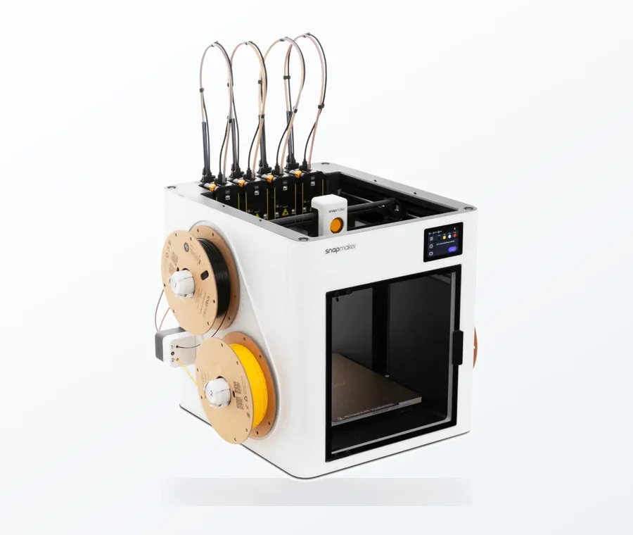
The consumer toolchanger 3D printer: the SnapSwap 4-toolhead system swaps heads in 5 seconds for true multi-color and multi-material printing, with smart calibration and auto filament loading.
- 4 toolheads · 5 s swap
- Up to 500 mm/s · 20,000 mm/s²
- 270 mm cube build volume
- Multi-color & multi-material
Print it or machine it: quick checklist
- Size: does the tool fit your build volume, or split into parts you can bond?
- Quantity: one to about a hundred copies? Printing fits. Larger runs may be cheaper by other methods.
- Accuracy: is ±0.13 mm enough? If only a few features need more, print undersized and machine those.
- Temperature: will the tool stay at least 28 °C below the material’s heat deflection temperature (HDT)?
- Chemicals: is the plastic compatible with the coolants and cleaners used at that station?
- Wear and load: can inserts, bushings or hardened pads take the abrasion and point loads?
If you answer yes to all six, a printed tool is worth a trial. Stratasys’ application guide reports average savings of 40–90% in lead time and 70–95% in cost for FDM jigs and fixtures. Treat these as vendor averages, not a forecast for your shop. For a traditional tool, the same guide estimates one to four weeks to design and build.

Which printing process suits which fixture
| Process | Materials used for tooling | Good for | Watch out for | Documented example |
|---|---|---|---|---|
| Desktop FDM | PLA, Tough PLA, PC, glass-filled nylon, TPU for soft contact pads | Assembly aids, badge and alignment jigs, low-force guides, fast iteration | Weaker between layers; PLA softens at low temperatures | Volkswagen Autoeuropa and Ford (UltiMaker) |
| Industrial FDM | ASA, PC, Nylon 12, Nylon 12 CF, ULTEM 9085 and 1010 | Heavier loads, higher temperatures, chemical exposure, CMM and inspection fixtures | Anisotropy; nylons and PC are sensitive to moisture | Volvo Trucks lifting devices and trim tools (Stratasys) |
| SLA (resin) | Tough resin | Small precise jigs with smooth surfaces | Check resin properties against loads and fluids | Pankl Racing Systems machining jigs (Formlabs) |
| SLS (nylon powder) | Nylon 12 and composites | Complex shapes and batches of tools; no support structures to remove | Depowdering adds labor | No case study used for this guide |
The Pankl example shows what SLA can hold. Its printed jigs met the ±0.1 mm tolerance on holes and length, and Tough Resin held up against the aggressive coolant used on the lathes. Each jig took 5–9.5 hours on a Form 2, and three printers produced about 40 jigs a week.
Choosing a fixture material: temperature, chemicals and creep
Stratasys says material should be the first decision in fixture design. Its tooling guide rates the common industrial FDM materials like this:
| Material | Loading | Temperature resistance | Chemical resistance |
|---|---|---|---|
| ASA | Light | Low | Low–moderate |
| PC | Moderate | Moderate | Low |
| FDM Nylon 12 | Light | Moderate | Moderate |
| FDM Nylon 12 CF | Heavy | Moderate | Moderate |
| ULTEM 9085 / 1010 | Heavy | High | High |
- Temperature rule: keep the tool at least 28 °C (50 °F) below the material’s HDT and 14 °C (25 °F) below its glass transition temperature. FDM parts contain residual stress and can warp as they approach these limits.
- Cleaners: ASA is attacked by ketones such as acetone and MEK. Nylon is vulnerable to strong acids, phenols and alcohols, including isopropyl alcohol. Both ULTEM grades resist most chemicals except phenols.
- Moisture and UV: Nylon 12, Nylon 12 CF and PC are the most water-sensitive of the group. The nylons are not UV-stable if left outdoors permanently.
- Creep: most tools are not loaded long enough to creep in use. Storage is the risk: a fixture stored under load can lose its critical dimensions.
On desktop printers the same logic applies at lower temperatures. UltiMaker’s examples match material to the job: Volkswagen Autoeuropa printed a wheel-nut guide in PLA because it sees no extreme forces, a bicycle pedal assembly tool is usually printed in polycarbonate for strength and rigidity, and UltiMaker’s own sliding-block press combines glass-fiber nylon (PA6 GF30) with TPU 95A so it does not damage the part. For a filament-level comparison see ABS vs PETG for high-stress functional parts and material selection for industrial additive applications.
Design rules for 3D printed jigs and fixtures

Strength and orientation
- Keep tensile loads in the XY plane. The bond between layers limits Z strength. In Stratasys’ FDM Nylon 12 CF example, ultimate tensile strength is 4,990 psi in Z against 10,960 psi along the layers. More on this in model orientation for strength.
- Orient critical features and surfaces in XY for the best accuracy and finish.
- Add radii and chamfers instead of sharp internal corners. Stratasys: the larger the radius or chamfer you can fit, the better the tool performs.
- Use variable infill. Stratasys’ bell crank example printed the press-fit bearing area solid, internal ribs at 30% sparse double-dense fill and the rest of the body at 60% sparse fill, with extra contours on the outside for rigidity.
Print time and supports
Orientation also sets print time. In Stratasys’ tooling guide, one tool took 6 h 23 min laid flat and 12 h 16 min standing up, with 3.0 in³ vs 4.2 in³ of support material.
- Design self-supporting angles steeper than 45° from the build plate. The default self-supporting angle in Stratasys’ software is 40–45°.
- For horizontal holes, model a slightly undersized diamond-shaped pilot hole. It prints without support and can be reamed to size.
- Avoid tapered walls where possible, and make wall thickness an even number of toolpath contours to prevent internal gaps.
Accuracy, hardware and wear
- Measure a first sample and offset surfaces. Where a feature prints oversized, offset its surfaces inward in CAD; where undersized, outward.
- Print location holes undersized and machine them, then press in metal or ceramic bushings where position matters.
- Use heat-set threaded inserts for fasteners. Stratasys prefers them over press-in inserts for torque-out and pull-out resistance. For printed threads, see designing functional printed threads.
- Add hardened rest pads where parts are loaded and unloaded repeatedly.
- Embed hardware during the print: model a pocket, pause the job, drop in a bushing, threaded insert, sensor or RFID tag, and resume. Magnets work too: Ford’s emblem jig holds magnets in printed holes to stay in place on the car.
Consolidation, bonding and ergonomics
- Merge assemblies into one part unless a split helps the operator or allows cheap replacement. Stratasys shows a lifting device with a 96% reduction in tooling assembly components. Volkswagen Autoeuropa did the opposite on purpose: its wheel-nut guide is printed in several parts so a damaged section can be reprinted alone.
- Bonding: Stratasys uses a 0.005 in (0.13 mm) adhesive gap as standard, mostly with epoxy.
- Add handles, part numbers and instructions directly on the tool. Stratasys notes that a lightweight, well-balanced, easy-to-handle design costs little or no extra time and money to print.
- Use topology optimization as a guide. Stratasys cautions that infill and layers make a printed part behave differently from the solid CAD model. Background: topology optimization for industrial components.
Jigs for a home workshop
The same rules apply to drilling guides, marking templates and clamp pads made on a desktop printer at home. Loads are lower than on a production line, but two things wear a home jig out faster than force: a drill bit or saw blade rubbing on plastic, and heat. The table gives material starting points based on Prusa’s material guides.
| Home jig | Starting material | Design tip |
|---|---|---|
| Drill guide, dowel or shelf-pin jig | PETG, which Prusa recommends for mechanical parts, holders and clamps | Do not let the bit run in bare plastic. Print the hole undersized and press in a steel drill bushing, the same rule Stratasys gives for location holes. |
| Marking templates, spacers, setup gauges | PLA is fine indoors | Prusa says PLA gets soft and deforms above 60 °C and breaks along layers on impact, so keep it out of hot cars and away from heat guns. Print the size or angle on the part. |
| Soft jaws, clamp pads, non-marring feet | TPU; Prusa lists spacing washers and high-stress parts as its best use | Print pads separately or combine them with a rigid body (see printing TPU with PLA or PETG) |
| Saw, router or track guides | PETG or ASA; Prusa gives ASA temperature resistance up to 93 °C and high impact and wear resistance | The guide edge should run against the tool’s base or fence, never against the blade or bit. Clamp it down rather than holding it by hand. |
| Jigs used or stored outdoors | ASA, which Prusa describes as UV resistant and suited to outdoor use | Avoid PLA, which Prusa says degrades under UV light |
- Walls and infill: Prusa’s flexible-materials guide advises more infill and more perimeters when a part needs better mechanical resistance. For a jig that gets clamped or knocked, start with extra perimeters around holes and edges, then check the first print under real use before printing more.
- Check downloaded designs against your tool. Drill guides and saw jigs on model libraries are drawn for someone else’s bit size, fence or track. Measure your own and adjust the model before you print a batch.
- Power tools: a printed guide positions the tool; it should never be the only thing holding the workpiece against a moving blade. Follow the tool manufacturer’s instructions and wear eye protection.
What manufacturers report after switching
- Volkswagen Autoeuropa (UltiMaker): a wheel protection jig went from €800 sourced to €21 printed, with development time cut from 56 to 10 days. A window gauge dropped from €180 to €35 per part. New tools are printed overnight and tested on the line the next morning.
- Pankl Racing Systems (Formlabs): machined jigs cost €40–50, and complex ones up to €300. Printed versions cost €8.50–25, with lead time down from two to three weeks to less than a day.
- Ford Cologne pilot plant (UltiMaker): an emblem positioning jig printed in Tough PLA, which UltiMaker describes as soft enough to avoid scratching the bodywork, made in two parts and glued.
Printed fixture problems: cause and fix
| Symptom | Likely cause | Fix |
|---|---|---|
| Tool warps or loses shape near a heat source | Service temperature too close to HDT or Tg | Choose a material whose HDT is at least 28 °C above the service temperature |
| Cracks or splits between layers | Tensile or bending load across the layers | Reorient so the load runs in XY, add radii, add contours |
| Location holes off or too tight | Normal FDM tolerance | Print undersized, ream or machine, press in bushings |
| Contact points wear quickly | Abrasion from repeated loading | Hardened rest pads or metal inserts at wear points |
| Surface softens or crazes after cleaning | Cleaner not compatible (e.g. acetone on ASA) | Change cleaner or switch material |
| Dimensions drift between uses | Creep while stored under load | Store unloaded; check critical dimensions before use |
| Drill guide hole wears oval or the bit wanders | Bit running directly in plastic | Press in a steel drill bushing |
| Tool marks the product | Hard plastic on a finished surface | Add TPU pads, or use a softer material as Ford did |
Common mistakes and next steps
- Copying a machined design one-to-one. Stratasys lists sticking to traditional design practice as the first adoption obstacle. Redesign for printing: consolidate, remove mass, add features.
- Printing with default slicer settings. Adjust walls, infill and orientation per tool.
- Starting with the hardest tool. Stratasys advises starting with simple applications and moving to demanding tools as experience grows.
- Treating the first print as final. Get operator feedback and revise; that fast loop is where most of the value comes from.
Frequently asked questions
What is the difference between a jig and a fixture?
A jig guides a tool, such as a drill or trim guide. A fixture holds and locates the workpiece while you machine, assemble or inspect it. Both can be printed, and the same design rules apply.
Are 3D printed fixtures accurate enough for production?
Stratasys states that FDM fixtures easily reach ±0.13 mm (0.005 in), and Pankl’s SLA jigs met a ±0.1 mm tolerance on holes and length. If a few features need more, print them undersized and machine them, or press in bushings.
What is the best filament for jigs and fixtures?
It depends on load, temperature and chemicals at the workstation. For light assembly aids, manufacturers use PLA or Tough PLA; for strength and rigidity, PC or fiber-filled nylon; for high temperatures and chemical exposure, ULTEM. Check the material’s HDT and keep the tool at least 28 °C below it.
How much do 3D printed jigs save?
Published cases show large savings, such as €800 to €21 at Volkswagen Autoeuropa, and Stratasys reports average cost savings of 70–95%. These are manufacturer-selected successes. Compare against your own machining or outsourcing quotes, including the printer’s running costs.
Sources
- Stratasys design guide: Design considerations for FDM additive manufacturing tooling (PDF)
- Stratasys technical application guide: FDM for jigs and fixtures (PDF)
- UltiMaker: Application focus, jigs and fixtures
- UltiMaker: Volkswagen Autoeuropa 3D printed tools, jigs and fixtures
- Prusa Knowledge Base material guides: PLA, PETG, ASA and flexible materials
- Formlabs: Reducing costs and lead time with 3D printed jigs and fixtures (Pankl Racing Systems)