Mechanical binding is extra resistance in a printer’s motion system: a spot where the print head, gantry or bed drags or sticks instead of gliding, because a part is misaligned, over-tightened, worn or dirty. The quickest way to find it is by hand. Switch the motors off, move each axis slowly along its full length in both directions (on X/Y also along both diagonals, as Prusa suggests), and note where it tightens. Resistance at one spot points to alignment or a bent part; resistance everywhere points to over-tightened wheels, bearings or dry parts.
Binding matters because the motors have to push through it. Enough drag and a stepper skips, which shows up as a layer shift; a milder drag shows up as noise, uneven walls or wrong dimensions. This guide covers the hand test, eccentric nuts on V-slot wheels, the Z lead screw and coupler, smooth rods, linear rail preload and how to read what you find. The procedures come from Prusa, Creality, Sovol and HIWIN documentation linked at the end.
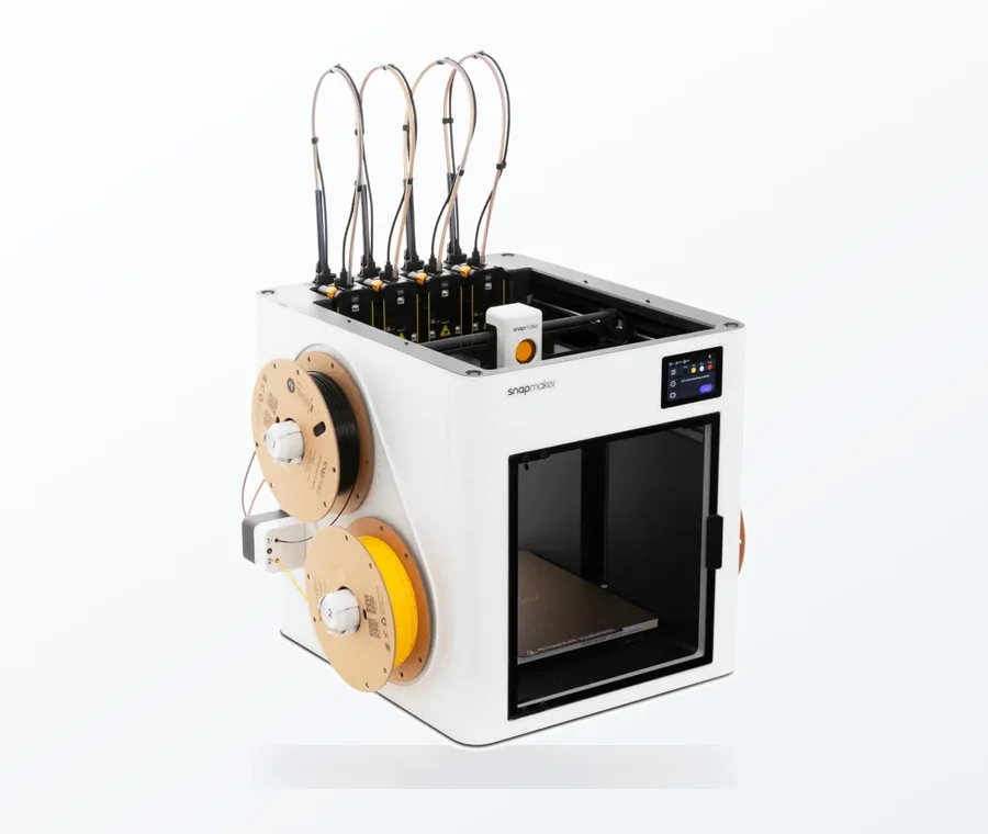
The consumer toolchanger 3D printer: the SnapSwap 4-toolhead system swaps heads in 5 seconds for true multi-color and multi-material printing, with smart calibration and auto filament loading.
- 4 toolheads · 5 s swap
- Up to 500 mm/s · 20,000 mm/s²
- 270 mm cube build volume
- Multi-color & multi-material
Binding check in 60 seconds
- Let the printer cool, then disable the motors from the menu or switch the printer off.
- Push the print head along X and the bed or head along Y, slowly, end to end. Then try both XY diagonals.
- Turn the Z lead screw or screws by hand (or lift the gantry, if your printer allows it) through the full height.
- Note where the resistance changes, clicks or catches, and whether it is at one spot or along the whole axis.
- Look for the obvious first: filament scraps, a cable bundle or zip tie rubbing the frame, a pulley touching the motor.
- Use the diagnosis table below to go to the right fix, and change one thing at a time.
Symptoms of binding and where to look
Binding rarely announces itself in the print as “binding”. It looks like other faults, which is why the hand test comes first. Prusa’s layer shift guide puts obstacles, cable bundles, pulleys and scratched rods on the same checklist as belts, and asks you to test the axes both from the menu and by hand with the printer cold and off.
| What you notice | Likely cause | Fix |
|---|---|---|
| Axis tight at one spot, free elsewhere | Bent rod or lead screw, misaligned rail or rod holder, debris | Roll-test the rod or screw; realign holders; clean |
| Axis evenly stiff along its whole length | Eccentric nuts or bearing clamps too tight, dry bearings, rail block with high preload | Back off the eccentric nuts or clamp screws; clean and lubricate |
| Carriage wobbles or clunks when rocked | Eccentric nuts too loose, worn wheels or bearings | Tighten until play just disappears; replace worn parts |
| Layer shift at the same height or position in every print | A tight spot the motor cannot push through | Find it with the hand test; then check belts and pulleys |
| Regular horizontal banding on walls | Lead screw not straight or not aligned with the motor, loose coupler, clamped Z nut | Roll-test the screw; loosen and re-seat motor, nut and top mount; tighten coupler |
| Squeak, scrape or grinding on one axis | Dry or dirty rods, wheel rubbing, pulley pressed against the motor | Clean, lubricate per manufacturer, space the pulley correctly |
| Gantry lower on one side (dual Z) | The two lead screws out of step or not parallel | Measure both sides from the base and even them out |
V-slot wheels and eccentric nuts
On printers that roll on V-wheels in aluminium extrusions (Creality Ender-style machines and many others), some wheels sit on eccentric nuts: hex spacers whose hole is off-centre, so turning them moves the wheel into or away from the groove. They are the most common source of binding that the owner caused.
- Clean first. Creality’s Ender-3 V2 manual asks you to check that the extrusion grooves and the wheel surfaces are clean before adjusting.
- Find the eccentric wheels. They are the ones with a hex spacer instead of a plain bolt, usually on one side of each carriage.
- Turn the spacer with the supplied spanner in small steps until the wheels touch the groove with minimal play but are not too tight, as the manual puts it.
- Check both ways. Rock the carriage: no clunk. Push it along the axis: it should roll evenly with no tight spot. A common practical check is that you can still turn a wheel with your fingers while the carriage is in place.
- Re-check after a few prints and adjust again if play has come back.
Creality’s warning is worth taking literally: wheels that are too tight wear much faster and can stick at points along their travel. A wheel with a flat spot or a worn edge will bind or clunk once per revolution however you set the nut, so replace it. If you keep fighting the wheels, our comparison of linear rails vs V-rollers covers when a conversion is worth it.
Z axis: lead screw, coupler and Z nut alignment
The Z axis binds when the lead screw, the motor shaft and the nut on the gantry or bed are forced out of line. The screw is held at up to three points (coupler, nut, and on many printers a top bearing), and if those points do not sit on one straight line something has to bend. Sovol’s Z-wobble guide gives the basic checks:
- Check the screw is straight. Remove it and roll it on a flat surface. If it wobbles or rocks, replace it.
- Check the coupler. A loose coupler lets the axis shift; tighten its grub screws or replace it.
- Let everything find its line. Loosen the screws on the lead screw nut, the Z motor mount and the top mount. Move the axis through its full travel so the parts settle where the screw wants them, then retighten.
- Check the nut on its own. Unscrew the nut from its mount and run it along the screw by hand. If it is rough or tight on a straight screw, the nut is worn or damaged and should be replaced.
- Dual Z: measure from the base to the gantry (or smooth rod) on both sides and adjust the Z motors until the two sides match.
Whether the Z screws get lubricant depends on the printer. Prusa’s i3 maintenance guide says explicitly not to lubricate the trapezoid nuts or threaded Z lead screws, because lubricant collects dust and debris on the threads, while other makers specify grease. Follow your manufacturer; our lubrication guide has the details per part.
Smooth rods and linear bearings
Rod-and-bearing printers bind for two reasons: the bearings are squeezed out of round, or the two rods of an axis are not parallel. Prusa’s maintenance and vibration guides cover both:
- Feel the rods. Hold each rod between two or three fingers and move slowly from one end to the other while rotating around it. Check any scratch with a fingernail; a deep groove means a new rod.
- Do not over-tighten the bearing clamps. Prusa warns that over-tightening the screws on the X-carriage back or the U-bolts can deform the bearings and scratch the rods.
- Clean and lubricate. If movement is still rough, Prusa suggests removing the bearings and putting a pea-sized amount of lubricant inside, and avoiding high-viscosity lubricants.
- Align the rod holders. For the Y axis on the MK3S, Prusa loosens the M3x10 screws on the rod holders by half a turn, moves the bed along its full travel so the rods settle, then tightens the front screws followed by the rear ones. The same idea works on most rod-based axes.
Linear rails: preload vs binding
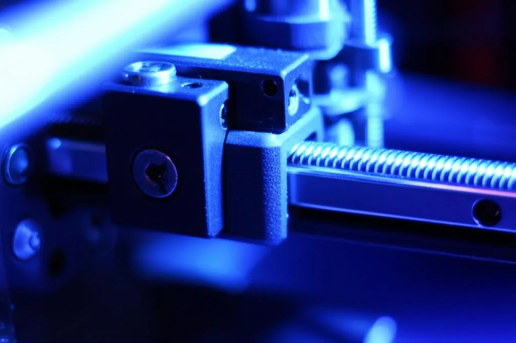
A linear rail block is supposed to have some drag. Rail makers sell blocks in preload classes; HIWIN lists its miniature MGN blocks as ZF (slight play), Z0 (very light preload) and Z1 (light preload). A higher-preload block feels stiffer along the whole rail, and that is by design. Binding is different: a block that runs freely and then tightens at one spot, or only when the second rail is bolted down.
- Tight at one spot: the rail is bowed where it is bolted to an extrusion that is not straight, or there is debris in the block. Loosen the rail screws, push the block along it and retighten from one end.
- Free alone, tight with two rails: the rails are not parallel. Fix one rail, then align the second while moving the carriage across the full travel.
- Rough or gritty everywhere: dry or contaminated. HIWIN notes that its guideways, like any rolling bearing, need an adequate supply of grease or oil.
Choosing a preload class, fitting rails to extrusions and running two rails in parallel are covered in the rail upgrade guide.
Belts, pulleys and the frame
Some drag comes from parts that are not guides at all. Prusa’s vibration guide points to pulleys pressed against the motor body, which create resistance, and belts that rub on plastic parts. Check that each pulley has a small gap to the motor face and that its grub screw sits on the flat of the shaft. A belt that is far too tight also loads the bearings and motor shafts; see belt tension and layer shifts for how to set it.
A frame that is out of square forces the gantry to bend as it moves, so it binds at one end of its travel whatever you do to the wheels or rails. If the hand test shows the gantry tightening towards the top or one side, check the frame first: our guide to squaring and bracing the frame covers diagonal measurements and bolts.
Common mistakes when fixing binding
- Tightening everything. Most binding is caused by clamping too hard: eccentric nuts, bearing clamps, Z nut screws. Adjust towards “just no play”, not “as tight as possible”.
- Lubricating a misalignment. Oil hides the feel of a tight spot for a while; it does not straighten a rod or square a frame.
- Testing with the motors on. Energised steppers hold their position, so you feel the motor, not the mechanics. Disable them first.
- Changing three things at once. If the axis improves, you will not know which change did it, and one of the others may have made something else worse.
- Stopping at the mechanics. If every axis now moves freely and layers still shift, the cause is elsewhere: belts and pulleys, motor current, acceleration or overheating drivers. Work through layer shift causes next.
Frequently asked questions
How do I know if my 3D printer axis is binding?
Disable the motors and move the axis slowly by hand along its full length in both directions. A healthy axis feels the same all the way; binding feels like a tight spot, a catch or uneven resistance. Listen too: squeaks or scraping during prints often come from the same place.
Can mechanical binding cause layer shifts?
Yes. If the resistance is more than the stepper motor can push through, it skips steps and the rest of the print is offset. A shift that happens at the same position in every print points to a tight spot on that axis, while random shifts are more often belts, pulleys or motor settings.
How tight should the eccentric nuts be?
Just tight enough that the carriage has no play when you rock it, and no tighter. Creality describes it as minimal play but not too tight, and warns that over-tightened wheels wear faster and stick along their travel. You should still be able to roll the carriage smoothly by hand.
Should I remove the top bearing on the Z lead screw?
Try loosening it before removing it. Loosen the top mount, the Z motor mount and the nut screws, run the axis through its full travel so the parts align, then retighten. If the screw is bent, no mount setting will help and the screw needs replacing.
Sources
- Prusa Knowledge Base: Layer shifting
- Prusa Knowledge Base: i3 printers regular maintenance
- Prusa Knowledge Base: Vibration when printing (MK3S+/MK2.5S)
- Creality Ender-3 V2 user manual: Adjusting the V rollers
- Sovol: How to fix Z-wobble (lead screw, coupler, frame)
- HIWIN: MGN miniature guide block (preload classes)