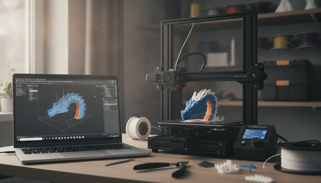
You’ve finished a model in Fusion 360, Blender, or downloaded one from Printables, and now you’re staring at an export dialog wondering which format to pick and why your slicer keeps throwing warnings. This is the point where most beginners either get lucky or get a spaghetti mess on the bed. The gap between a clean CAD file and a print that actually finishes isn’t luck — it’s a short, repeatable checklist that catches the same five or six problems every time. Walk through it once, and you’ll stop guessing why prints fail before the first layer even finishes.
Check your model before you even think about exporting
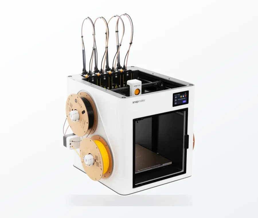
The consumer toolchanger 3D printer: the SnapSwap 4-toolhead system swaps heads in 5 seconds for true multi-color and multi-material printing, with smart calibration and auto filament loading.
- 4 toolheads · 5 s swap
- Up to 500 mm/s · 20,000 mm/s²
- 270 mm cube build volume
- Multi-color & multi-material
Every slicing failure that looks mysterious usually traces back to a mesh problem that existed before the file ever left your modeling software. The three things worth checking every single time: watertightness, correct scale, and consistent normals.
A watertight (manifold) mesh has no gaps, no duplicate faces, and no edges shared by more than two triangles. Non-manifold geometry confuses the slicer’s algorithm for deciding what’s “inside” versus “outside” the object, which shows up as missing walls, holes in the top surface, or a slicer error refusing to generate a preview at all. If you modeled in a solid-based CAD tool like Fusion 360, SolidWorks, or Onshape, this is rarely an issue because the software enforces solid bodies by construction. If you sculpted in Blender, ZBrush, or hand-edited a mesh in Meshmixer, it’s a real risk — Blender’s built-in 3D Print Toolbox add-on (enable it in Preferences > Add-ons) will flag non-manifold edges, intersecting faces, and flipped normals in one click.
Scale mistakes are the second most common trap, especially with files sourced online. STL files carry no embedded unit — a value of “1” could mean 1mm or 1 inch depending on what the original modeler assumed. If a model that should be a 60mm phone stand imports at 1524mm, someone modeled in inches and your software is reading it as millimeters (25.4x off is the signature of this exact mistake). Always check the bounding box dimensions in your slicer before printing, not after.
Finally, check face normals point outward. Inverted normals make a slicer think solid material is empty space, producing missing infill or walls that print as a shell with holes. Meshmixer’s Analysis > Inspector tool and PrusaSlicer’s built-in repair (right-click a model > Fix through the Netfabb-based repair service) both catch and fix this automatically in most cases.
Exporting to STL, OBJ, or 3MF — which format actually matters here
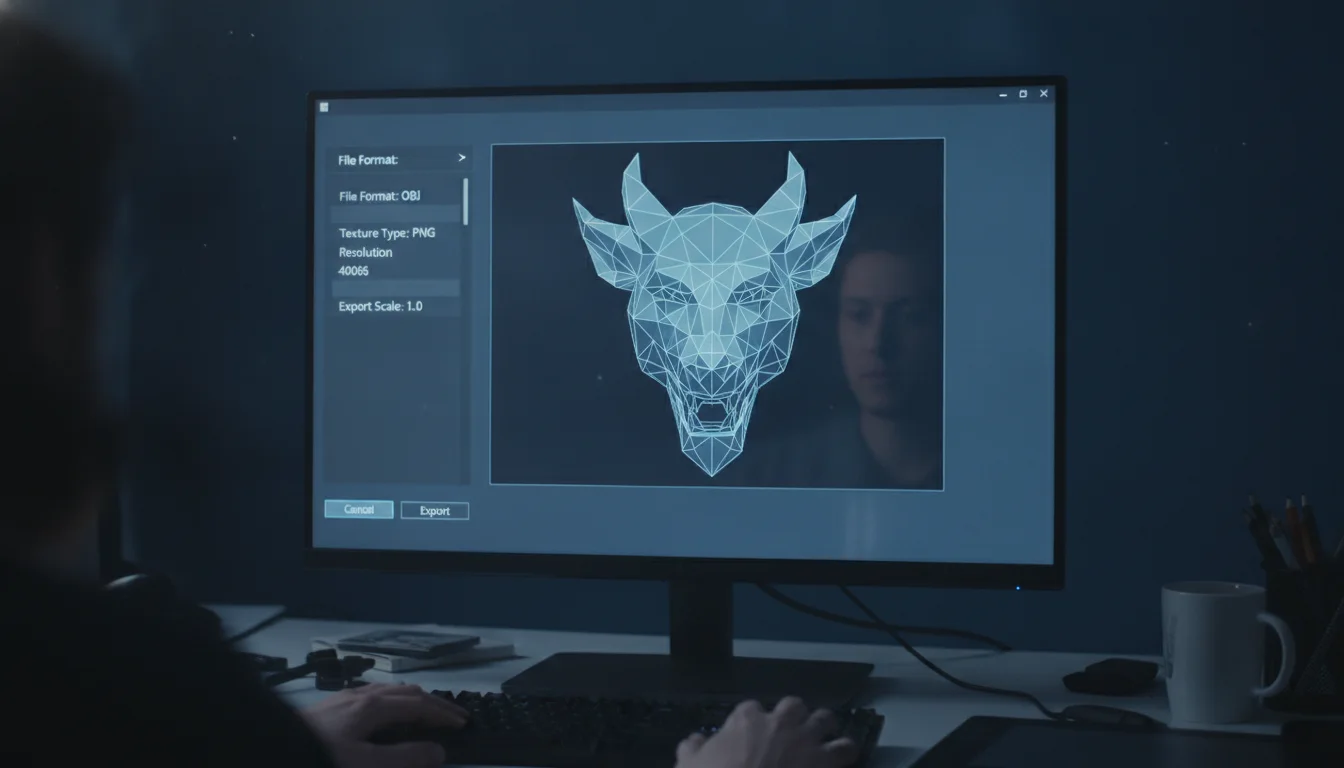
STL has been the default for FDM and resin printing for decades, and it still works fine for single-color, single-material parts. It stores raw triangulated geometry only — no units, no color, no multi-body assemblies. When exporting STL from Fusion 360 or Solidworks, pay attention to the mesh refinement setting (often called “resolution” or controlled by a chordal tolerance value). A tolerance of 0.01mm gives smooth curves but bloats file size and can slow down slicing on complex models; 0.05–0.1mm is a reasonable default for most functional parts, and you only need finer than that for small text or intricate curved surfaces that will be visible up close.
OBJ carries more information — colors, textures, and multiple objects — but slicer support for those extras is inconsistent, and most FDM users get no real benefit over STL unless they’re specifically doing multi-material work in software that reads OBJ color data well.
3MF is the format worth switching to if your slicer supports it (PrusaSlicer, Bambu Studio, and OrcaSlicer all do natively). It preserves units unambiguously, keeps multiple objects and their relative positions in one file, stores per-object print settings, supports painted color/support regions, and produces smaller files than STL for the same geometry because it uses more efficient encoding. If you’re exporting an assembly of parts that need to print together in a specific arrangement, or a model with slicer-side paint-on supports already applied, 3MF avoids the round-trip data loss that STL forces.
Whichever format you choose, export in binary rather than ASCII STL if given the option — binary files are a fraction of the size and load faster, with zero quality difference.
Loading into your slicer and getting orientation right
Drop the file into PrusaSlicer, Bambu Studio, Cura, or OrcaSlicer and resist the urge to slice immediately. Orientation decides layer adhesion direction, support volume, and surface finish more than almost any other single choice.
The rule of thumb: orient the model so the largest flat face sits on the bed for adhesion, and so load-bearing forces run along the print’s Z-axis as little as possible — FDM parts are inherently weaker between layers than within a layer, so a bracket that will be pulled apart should have its layer lines running perpendicular to the pulling force, not parallel to it. For a part with a natural front-facing surface (a figurine’s face, a sign’s text), orienting that surface upward or angled toward the nozzle path avoids the visible layer stepping you’d get printing it flat against the bed.
Supports come next. Most slicers default to generating supports wherever an overhang exceeds a 45° threshold from vertical, though this is adjustable — PrusaSlicer and OrcaSlicer let you push that to 50–55° for printers with good cooling and rigid PLA, since real overhangs often print cleanly steeper than the conservative default assumes. Tree/organic supports (available in PrusaSlicer, Cura, and Bambu Studio) use far less material and are easier to remove than grid supports for organic shapes, but grid supports remain more reliable under large flat overhangs where tree supports can wobble. Turn on “support on build plate only” unless the geometry genuinely needs support material touching the model itself — supports that touch the print leave visible scarring no matter how carefully you sand them.
Check the build plate boundaries too. A model that clips the printable area gets silently repositioned or rejected depending on the slicer, and it’s easy to miss on a cluttered plate with multiple parts.
Slicing settings that decide whether the print actually survives
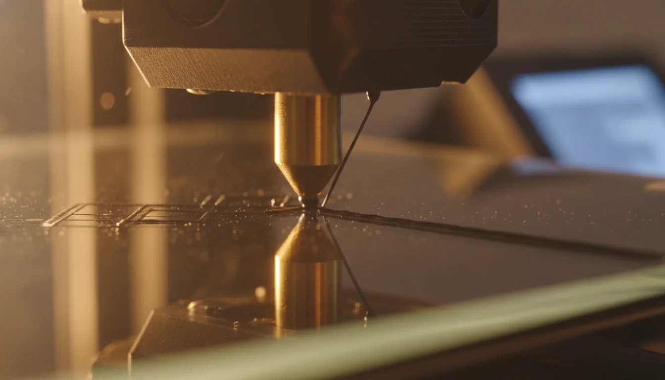
With orientation and supports sorted, the settings that matter most for a first successful print are layer height, wall count, infill, and first-layer setup — in roughly that order of impact on outcome.
Layer height of 0.2mm is the sensible default for a 0.4mm nozzle (the most common size on printers like the Prusa MK4, Bambu Lab P1S, and Creality Ender 3 V3) — it balances speed and detail well enough that you rarely need to deviate for a first print. Save 0.12mm or finer for parts where surface finish genuinely matters, since it roughly doubles print time.
Wall count (perimeters) should be at least 3 for anything that needs real strength, and 2 is the minimum for purely decorative prints. Two walls at 0.4mm nozzle width gives about 0.8mm of shell thickness, which is thin enough to fail under load-bearing stress on functional parts. Infill of 15–20% gyroid or cubic pattern is a reasonable default for most prints; push to 40–50% only for parts under genuine mechanical load, since infill above roughly 50% gives diminishing strength returns for a large time and material cost.
First-layer settings deserve outsized attention because a failed first layer is the single most common reason a beginner’s print fails outright. Slow the first layer speed down (many profiles default to 20–30mm/s versus 60mm/s+ for the rest of the print), and use a brim of 5–8mm for any model with a small footprint relative to its height — a tall, narrow vase-mode print without a brim is a near-guaranteed warping or tip-over failure. Bed temperature and a clean, correctly-leveled bed matter more than any slicer setting here; no software setting compensates for a bed that isn’t level or a surface with old glue residue and grease.
Reading the G-code preview before you commit to the print
The consumer toolchanger 3D printer: the SnapSwap 4-toolhead system swaps heads in 5 seconds for true multi-color and multi-material printing, with smart calibration and auto filament loading.
Every slicer generates a visual preview of the toolpath before it writes G-code to the printer or SD card — use it. Scrub through the layer-by-layer preview looking for three specific things: flying or disconnected extrusions (a sign of a mesh error that survived your earlier check), unsupported bridges longer than about 5–8mm printing without any support structure beneath them, and support structures that look sparse or disconnected from the bed.
Check the estimated print time and filament usage against what you expect — a wildly higher-than-expected time or material estimate is often the first sign that infill, supports, or wall count got set higher than intended, or that a stray duplicate object is hiding off the visible plate. Look at the retraction settings if you’re seeing stringing in past prints from the same material: 0.8–1.2mm retraction distance at 25–45mm/s is a common starting range for direct-drive extruders, while Bowden setups typically need 3–6mm to clear the longer tube.
Finally, confirm the printer profile itself matches your actual hardware — nozzle diameter, bed size, and start G-code all need to be correct, especially if you imported a profile shared online for a different printer. A 0.6mm nozzle profile sliced for a 0.4mm nozzle will under-extrude across the entire print in a way that’s easy to misdiagnose as a filament or temperature problem when it’s really just a mismatched profile.
Run through this sequence — mesh check, format choice, orientation and supports, core slicing settings, G-code preview — and most of the failures that make beginners think 3D printing is unreliable simply stop happening. None of it is complicated once it’s a habit; it just has to happen in order, every time, before you hit the print button.
Frequently asked questions
How do I fix an STL file that my slicer says is “non-manifold” or has holes?
If you modeled in Blender, enable the 3D Print Toolbox add-on (Preferences > Add-ons) to flag non-manifold edges, intersecting faces, and flipped normals in one click. Alternatively, load the file into Meshmixer and use the Analysis > Inspector tool, or right-click the model in PrusaSlicer and select “Fix through the Netfabb-based repair service” — both automatically repair most common mesh errors.
Why did my model import at the wrong size in my slicer?
STL files carry no embedded unit information, so a value of “1” could mean 1mm or 1 inch depending on the original modeler’s assumption. If a model that should be 60mm imports at 1524mm, someone modeled in inches and your software read it as millimeters — the exact signature of this mistake is a 25.4x size difference. Always check the bounding box dimensions in your slicer before printing.
Should I use tree supports or grid supports for my model?
Tree (organic) supports use far less material and are easier to remove than grid supports for organic shapes, making them the better choice for figurines or curved surfaces. Grid supports remain more reliable under large flat overhangs where tree supports can wobble, so use them for functional parts with broad flat sections. In either case, turn on “support on build plate only” unless the geometry genuinely needs support touching the model itself, since supported surfaces leave visible scarring.