
Every 3D modeling program, from Tinkercad to Fusion 360 to SolidWorks, is built on the same small set of operations underneath its own menus and icons. Learn those operations well and you can follow almost any tutorial regardless of which software it uses, because the logic transfers even when the buttons don’t. Skip them and you end up copying click-by-click instructions from videos without understanding why any given step works, which falls apart the moment your part is slightly different from the example. This guide covers the five tools that matter most for someone designing parts meant to actually be printed — brackets, enclosures, jigs, and fixtures that need to fit together and survive real use, not just render nicely on screen.
Sketch and constrain: the 2D foundation everything else builds on
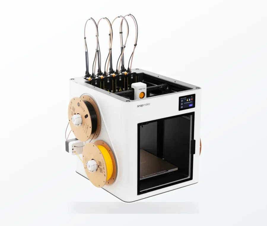
The consumer toolchanger 3D printer: the SnapSwap 4-toolhead system swaps heads in 5 seconds for true multi-color and multi-material printing, with smart calibration and auto filament loading.
- 4 toolheads · 5 s swap
- Up to 500 mm/s · 20,000 mm/s²
- 270 mm cube build volume
- Multi-color & multi-material
Almost every solid you will ever model for FDM or resin printing starts life as a flat 2D sketch on a plane, which then gets extruded, revolved, or swept into three dimensions. This is true in parametric CAD like Fusion 360, FreeCAD, and SolidWorks, and it’s true even in simplified tools where the sketching step is hidden behind a shape picker. If you only learn one habit early, make it this one: draw rectangles, circles, and lines, then lock them down with constraints and dimensions instead of eyeballing sizes by dragging.
Constraints are the rules that keep a sketch from collapsing when you change a dimension later. Coincident forces two points to sit on top of each other, tangent keeps a line touching a circle smoothly, parallel and perpendicular lock the angle between two lines, and symmetric mirrors a point pair across a centerline. A properly constrained sketch turns solid black (in Fusion 360) or green (in FreeCAD’s Sketcher) once every point has zero remaining degrees of freedom. An under-constrained sketch is the single biggest cause of parts that quietly change shape after you edit an unrelated feature three steps later in the timeline.
Tinkercad skips explicit constraints in favor of a snapping grid and numeric input boxes, which is fine for simple boxes and holes but breaks down once you need a hole centered exactly between two other features. If you’re using Tinkercad as a first tool, get comfortable with its ruler and the “align” command before moving to a parametric package — it teaches the same spatial thinking without the constraint vocabulary.
Extrude and revolve: turning flat profiles into printable volumes
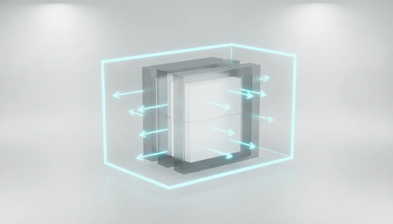
Extrude pushes a closed 2D profile straight along an axis to create a solid — a rectangle becomes a box, a circle becomes a cylinder. It’s the single most-used command in any modeling session, and most software gives you options worth knowing: extrude to a specific distance, extrude symmetrically in both directions from the sketch plane, or extrude up to another surface so the height updates automatically if that surface moves. For a printable enclosure wall, extruding “up to” the inside face of a lid rather than typing a fixed height means the two parts stay matched even after you tweak the lid’s thickness.
Revolve does the same job but rotates a profile around an axis instead of pushing it in a straight line, which is how you model anything round in cross-section — knobs, spacers, bottle-style containers, threaded standoffs before you add the actual thread. A half-profile of a doorknob, revolved 360 degrees around its centerline, produces a perfectly round part with a fraction of the sketch geometry a full 3D sculpt would need. Both commands also support “cut” mode, where instead of adding material they remove it — useful for machining a counterbore for a socket-head screw without drawing a second solid and subtracting it manually.
One printability detail worth internalizing here: a plain extrude with vertical walls is what your slicer treats as a 90-degree overhang at the base, which is not a problem, but any feature that extrudes outward past the layer below it will need support past roughly 45 degrees from vertical in FDM. Knowing this while you’re still in the CAD sketch — not after slicing — lets you add a chamfered lead-in instead of discovering the support requirement in PrusaSlicer or Cura later.
Boolean operations: union, subtract, and intersect
Boolean operations combine two or more solids using set logic instead of manual sketching. Union merges bodies into one — say, a cylindrical boss merged with a flat base plate to make a single mounting post. Subtract removes the volume of one body from another, which is how you cut a screw hole, a battery compartment, or a snap-fit slot into an otherwise solid block. Intersect keeps only the volume shared by two bodies, which is less common day to day but useful for trimming a rough block down to the exact overlap of two reference shapes.
Subtract is the workhorse for anything that needs to hold hardware. For an M3 machine screw, subtracting a 3.4 mm diameter cylinder gives clearance for the screw to pass through freely; a self-tapping hole into printed plastic for the same screw is usually closer to 2.5–2.8 mm depending on your material and wall thickness, since the plastic threads form around a smaller pilot hole. Get the diameter wrong by even a few tenths of a millimeter and the part either won’t accept the screw or splits when you force it in — this is one of the few places in modeling where a number from a hardware chart matters more than eyeballing it.
Booleans also let you build complex shapes from simple primitives rather than fighting with sketch geometry. A phone stand’s cradle, for example, is often just two boxes unioned together and a third box subtracted at an angle to form the slot — three primitive shapes and two boolean operations, no freeform sculpting required. This primitive-plus-boolean approach is exactly how Tinkercad’s entire workflow is built, and it scales up fine into parametric tools once you need dimensions to stay editable.
Fillet and chamfer: rounding edges for strength and printability
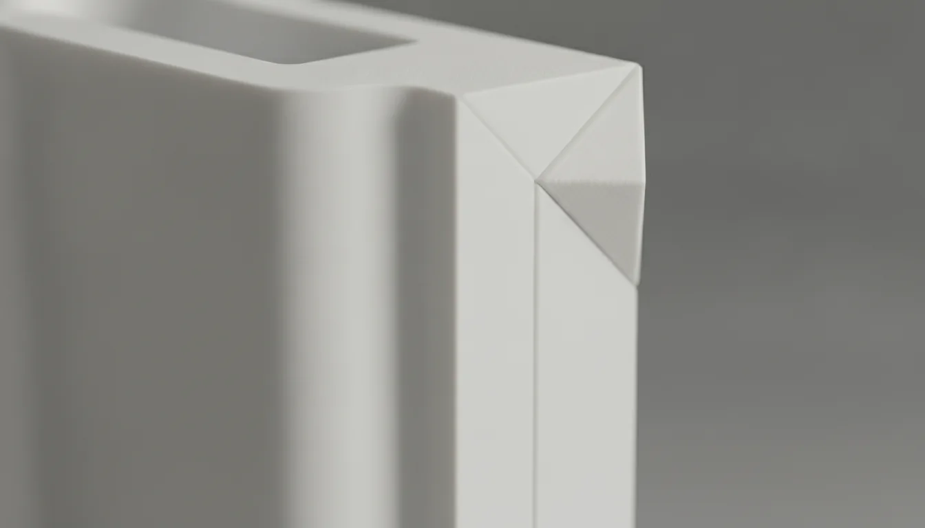
Fillet rounds a sharp edge into a smooth curved radius; chamfer cuts it into a flat angled bevel instead. Both look like cosmetic finishing touches, but they solve two real engineering problems. Sharp internal corners concentrate stress — a 90-degree internal corner on a bracket under repeated load is where cracks start, because stress lines can’t turn a sharp corner without piling up. A fillet as small as 1–2 mm at that internal corner spreads the load across a curve instead of a point and meaningfully increases the part’s fatigue life, which matters more than it sounds for anything that flexes, like a snap-fit tab or a living hinge.
Chamfer earns its keep on the print bed rather than under load. A small 0.4–1 mm chamfer on the bottom edge of a part that would otherwise sit flush on the build plate reduces elephant’s foot — the slight outward bulge FDM prints get at the first few layers from bed adhesion pressure — by giving the outline somewhere to taper into instead of a hard 90-degree step. The same trick on the top edge of a vertical hole prevents the drooping, slightly oval opening you get when a hole’s roof spans unsupported in one shot; a 45-degree chamfer lets each layer bridge a shorter gap than the one before it.
Don’t fillet or chamfer everything reflexively, though. Rounding every single edge on a mechanical part makes flat mating faces impossible to register against a fixture or another part, and it adds modeling complexity for no return on faces that will never be touched or stressed. Apply these tools with intent: structural corners get filleted, plate-facing edges get chamfered, purely decorative edges get whatever looks right.
Mirror and pattern: duplicating geometry without duplicating effort
The consumer toolchanger 3D printer: the SnapSwap 4-toolhead system swaps heads in 5 seconds for true multi-color and multi-material printing, with smart calibration and auto filament loading.
Mirror reflects a feature or body across a plane, which is the fastest way to build anything symmetric — model one half of an enclosure with its screw bosses and cable slots, mirror it across the centerline, and the second half is generated automatically and stays in sync if you edit the original. Pattern (sometimes called array) repeats a feature along a line, a grid, or around a circle at a set spacing or count. A rectangular pattern places a row of ventilation slots at even intervals; a circular pattern places four mounting holes evenly around a lid at 90-degree spacing without you calculating a single coordinate by hand.
The real value of both tools is what happens when you change your mind. If a hole pattern was drawn as four separate manually-placed circles and you decide you need six holes instead, you’re redrawing and repositioning by hand. If it was a circular pattern with a count parameter, you type 6 instead of 4 and every hole updates position automatically, still evenly spaced. This is the difference between a model you can iterate on in minutes and one you have to rebuild from scratch every time a requirement shifts — and requirements shift constantly once you start test-fitting printed parts against real hardware.
Mirror and pattern also keep file complexity down, which matters for slicing performance. A hundred bolt holes modeled as one circular pattern feature is one entry in the model tree; a hundred holes drawn individually bloats both the CAD history and, after export, the STL’s triangle count, which slows down the slicer’s mesh processing for no benefit.
Measure, check, and export: getting a model ready for the slicer
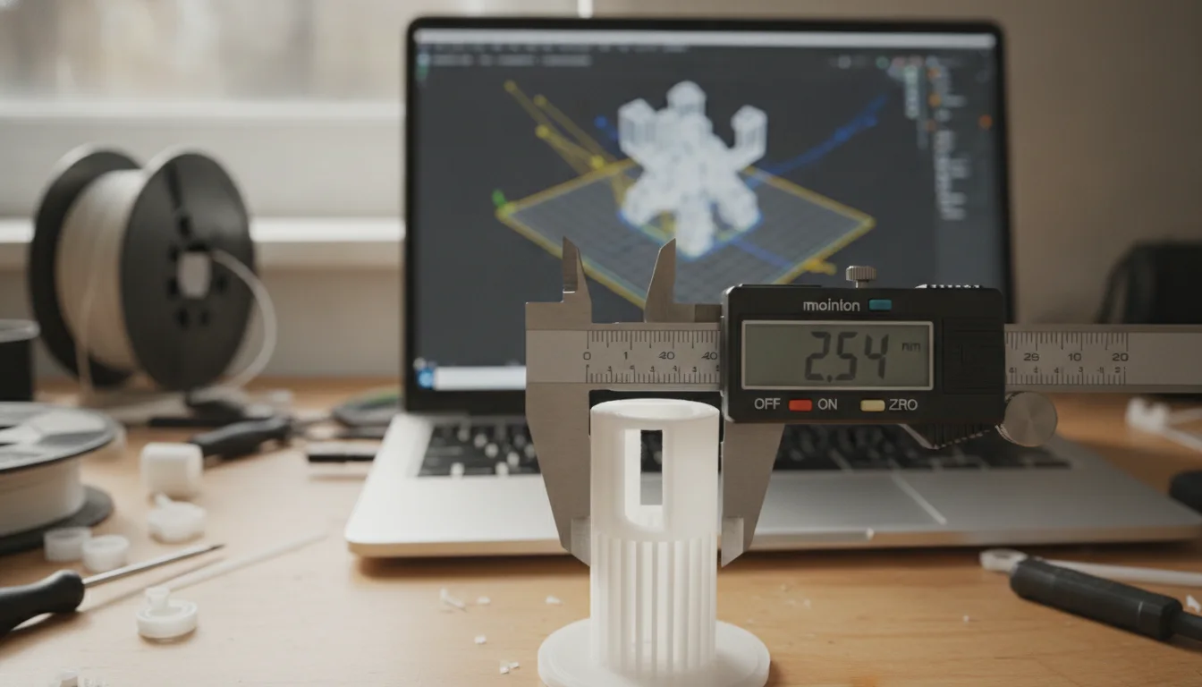
Before anything leaves your CAD software, the measure tool should confirm two things: overall dimensions match what you intended, and minimum wall thickness is printable. For FDM with a standard 0.4 mm nozzle, a single-wall feature thinner than about 0.8 mm will either get skipped by the slicer or printed as a fragile single line with no infill support; most practical minimums for a wall that needs any real strength sit closer to 1.2 mm, which lines up with three perimeter passes at a 0.4 mm line width. Resin printers tolerate thinner unsupported walls, often down to 0.4–0.5 mm, but thin resin walls are correspondingly more fragile to post-processing and cleaning, so “printable” isn’t the same as “durable” on either process.
Check your model for watertightness before export — every face needs to form a fully closed volume with no gaps, flipped normals, or overlapping shells, or the STL export will produce a non-manifold mesh that your slicer either rejects or silently repairs in a way you didn’t intend. Most parametric CAD tools flag this automatically as an error in the timeline; mesh-based tools like Blender need an explicit check, usually a “Merge by Distance” pass followed by inspecting for non-manifold edges before exporting.
On export, set your STL tessellation tolerance tighter than the default for anything with curves — a chord height around 0.01 mm (or the equivalent “high” preset) keeps circles and fillets looking round instead of faceted once they hit the print bed, at the cost of a larger file. If your workflow allows it, export STEP alongside STL for any part you might need to edit again; STEP preserves the parametric history and exact geometry, while STL is a fixed triangle mesh with no way back to the original sketch and features once it’s been generated.
Frequently asked questions
What is the most common mistake beginners make with constraints in a parametric CAD sketch?
The most common mistake is leaving a sketch under-constrained, which causes the entire part to change shape unpredictably when you edit an unrelated dimension later in the model timeline. A properly constrained sketch has zero remaining degrees of freedom, shown by all geometry turning solid black in Fusion 360 or green in FreeCAD’s Sketcher.
How do I choose between a fillet and a chamfer for a 3D printed part?
Apply a fillet (rounded radius) to internal structural corners under load, such as the inside of a bracket or a snap-fit tab, because it spreads stress and prevents cracks. Apply a chamfer (angled bevel) to the bottom edge of a part that sits on the build plate to reduce elephant’s foot, and to the top edge of vertical holes to prevent the opening from drooping or becoming oval during printing.
What minimum wall thickness should I design for in FDM vs. resin printing?
For FDM with a standard 0.4 mm nozzle, design walls at least 0.8 mm thick to avoid being skipped by the slicer, and preferably 1.2 mm for any part needing real strength — that matches three perimeter passes. Resin printers can handle thinner unsupported walls down to 0.4–0.5 mm, but those walls are much more fragile during post-processing and cleaning, so “printable” does not mean “durable” on either process.