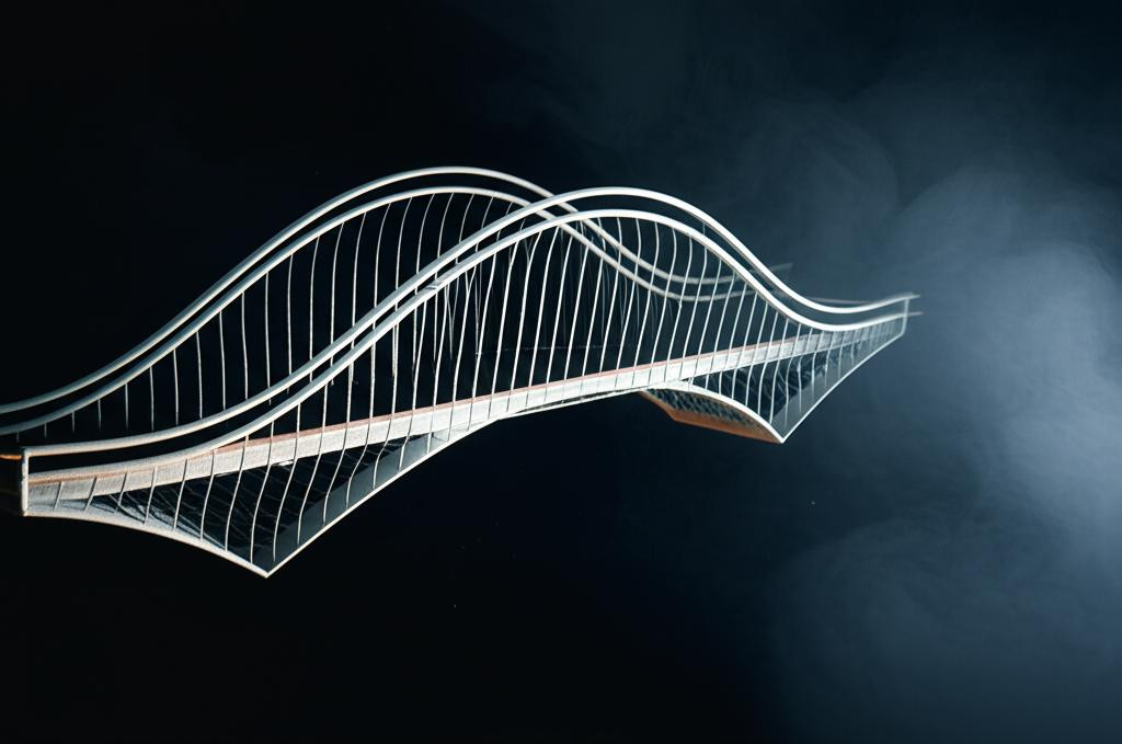
Bridging in 3D printing is often considered one of the trickiest maneuvers a printer can undertake. It involves extruding filament horizontally through the air, connecting two unsupported points without a solid layer beneath. The goal is to create a smooth, sag-free span, a feat that feels almost like magic when executed perfectly. However, for many, it's a source of frustration, leading to droopy lines, stringing, or outright print failures. The secret to transforming these challenges into triumphs lies not in hardware upgrades, but in the meticulous calibration of your slicer settings.
This guide will take a deep dive into the critical parameters that govern successful 3D printing bridges: flow rate, print speed, and cooling fan control. We'll unravel how each setting contributes to the structural integrity and aesthetic quality of your bridges, empowering you to fine-tune your printer for impeccable results. By understanding these nuances, you'll be well on your way to achieving bridging optimization, turning what was once a daunting obstacle into a routine success.
Understanding the challenge of bridging

Explore the
Snapmaker U1
At its core, bridging defies gravity. When your 3D printer lays down a normal layer, it's extruding molten plastic onto a solid, cooler surface, which provides immediate support and helps the plastic solidify. With a bridge, the filament is pushed into empty space. For the bridge to succeed, the extruded plastic must cool and solidify quickly enough to maintain its shape and tension across the gap before gravity pulls it down. This delicate balance is influenced by numerous factors, including the material's properties, ambient temperature, and, most significantly, the printer's slicer settings.
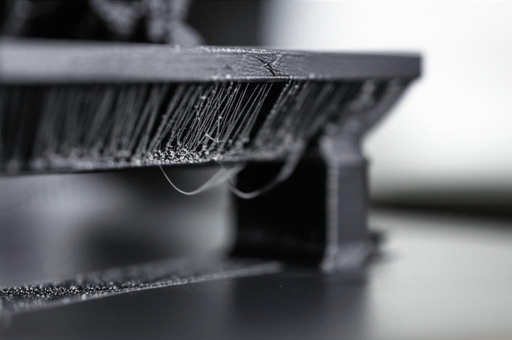
Common issues like sagging occur when the plastic remains molten for too long, allowing gravity to deform it. Stringing might arise from inadequate retraction or excessive nozzle temperature, leaving wispy strands across the gap. Poor adhesion to the anchor points can cause the entire bridge to detach or warp. Addressing these challenges requires a systematic approach to adjusting the parameters within your slicing software, ensuring that the printer acts as a precision architect, not just a dispenser of plastic.
Key slicer settings for bridging mastery
Bridging flow rate: calibrating for tension
The bridge flow rate, often expressed as a percentage or multiplier, dictates the amount of plastic extruded specifically during bridge sections. Unlike regular infill or perimeter lines, where a slight over-extrusion might simply lead to minor dimensional inaccuracies, over-extrusion on a bridge is a recipe for disaster. Too much material means more mass for gravity to act upon, inevitably leading to sagging and a messy, uneven surface. Conversely, under-extrusion can result in gaps, weak adhesion, or even broken lines that fail to span the distance.
The ideal bridge flow rate aims for a delicate balance: just enough material to create a continuous line that adheres well to the anchor points, but not so much that it sags. Many slicers default to 100% flow for bridges, but for optimal results, this often needs to be reduced, sometimes significantly. A common starting point for PLA, for instance, might be around 75-90%. This reduced flow rate creates a thinner, lighter strand of plastic that cools faster and has less material to sag. It also introduces a slight tension, allowing the plastic to stretch tautly across the gap rather than simply dropping. Experimentation with a dedicated bridge test print is crucial here, incrementally adjusting the flow rate until you achieve a flat, consistent bridge without gaps or excessive material.
Print speed for bridges: the race against gravity
The print speed at which your nozzle traverses a bridge is another critical factor. It's a balancing act: too slow, and the plastic spends too much time in its molten state, increasing the chances of sagging. Too fast, and the plastic may not have enough time to adhere properly to the previous line or the anchor points, leading to weak connections or complete failure. The goal is to lay down the plastic quickly enough to minimize sag, but slowly enough to ensure proper adhesion and cooling.
Many slicers allow you to specify a separate print speed for bridges, distinct from other print speeds like perimeters or infill. A good starting point for bridge speed is often slightly faster than your outer perimeter speed, but slower than your infill speed. For PLA, a bridge speed in the range of 20-40 mm/s is often effective. Faster speeds (e.g., 50-60 mm/s) can work for very short bridges or highly cooperative materials, but generally increase the risk of detachment or poor line formation. Slower speeds (e.g., 10-15 mm/s) are sometimes necessary for challenging materials like flexible filaments, but must be carefully balanced with cooling to prevent excessive sagging. Observing the print in action and making small, iterative adjustments to this setting will reveal the sweet spot for your specific printer and filament.
Cooling fan control: solidifying success
Perhaps the most impactful setting for successful bridges is the part cooling fan. When extruding into thin air, rapid solidification is paramount. The faster the plastic cools and hardens, the less time gravity has to pull it down, preventing sagging and ensuring the bridge maintains its intended shape. For this reason, it's almost universally recommended to run your part cooling fan at 100% when printing bridge sections, regardless of the material, unless specific material properties (like ABS warping) strongly advise against it.
Most modern slicers offer specific settings for bridge fan speed, allowing you to override the general fan speed for these critical sections. Ensuring your fan is directed effectively at the nozzle tip and the freshly extruded plastic is also vital. A well-designed part cooling duct can make a significant difference. While maximum cooling is generally desirable for bridges, be mindful of materials like ABS, which are prone to warping with sudden temperature changes. In such cases, you might need to find a compromise, perhaps 70-80% fan speed, and combine it with other optimizations. For PLA and PETG, however, crank that fan up to full power for your 3D printing bridges.
Other influential slicer settings for bridging optimization
Bridge line direction
The direction in which your slicer lays down the bridge lines can have a subtle yet significant impact. Most slicers will try to orient bridge lines along the shortest path between two anchor points. However, some advanced settings allow for manual control or offer options like aligning lines with the dominant direction of the gap. Laying lines perpendicular to the direction of the longest span can sometimes provide better support and reduce sag, as each line has a shorter unsupported segment. Experimenting with this setting, if available in your slicer, can offer an extra layer of bridging optimization.
Nozzle temperature
While not a dedicated bridge setting, your overall nozzle temperature plays a crucial role. Printing at the lower end of your filament's recommended temperature range can be beneficial for bridges. Cooler plastic solidifies faster, directly combatting sag. However, going too low can lead to under-extrusion, poor layer adhesion, and even nozzle clogging. It's a delicate balance. If you're struggling with bridges, try reducing your nozzle temperature by 5-10°C, but always ensure it's still hot enough for smooth extrusion and good inter-layer adhesion on other parts of your print. This adjustment, combined with optimized slicer settings for flow, speed, and cooling, can yield impressive results.
Layer height
Thinner layers generally mean less material per pass, which can be advantageous for bridging. A smaller layer height means each extruded line is lighter and has less volume to sag. It also allows for more lines to be laid down to cover the same gap, potentially creating a stronger structure. However, printing with very thin layers increases overall print time. For most situations, your standard layer height should work, but if you're facing persistent bridging issues on particularly challenging spans, consider a slight reduction in layer height as part of your bridging optimization strategy.
Retraction settings
While not directly affecting the structural integrity of the bridge itself, proper retraction settings are vital for preventing stringing and blobs on or around your bridges. Stringing can make an otherwise perfect bridge look messy and can even interfere with the cooling process. Ensure your retraction distance and speed are well-calibrated for your filament and hotend. This will minimize unwanted material deposition as the nozzle moves across the unsupported gap, contributing to cleaner, more aesthetically pleasing 3D printing bridges.
Perimeter overlap and infill
The way your bridge lines connect to the surrounding perimeters and infill can also impact their success. Adequate perimeter overlap ensures the bridge lines have a solid foundation to adhere to. Similarly, the infill pattern and density directly underneath a bridge's anchor points can provide better support. While not a direct bridge setting, ensuring your general infill and perimeter settings are robust will create a stronger framework for your bridges to connect to, indirectly aiding in their stability and appearance.
Calibration and testing for optimal results

Achieving perfect bridges is rarely a one-shot deal. It requires a systematic approach to calibration and iterative testing. The best way to dial in your slicer settings for bridges is by using dedicated bridge test models. These models typically feature various gap lengths and widths, allowing you to observe how your printer performs under different bridging scenarios.
Here’s a suggested approach:
- Start with a baseline: Begin with your slicer's default bridge settings or a known good profile for your filament type.
- Isolate variables: Focus on adjusting one setting at a time. For instance, start with bridge flow, keeping speed and fan constant.
- Print and observe: Print a bridge test model after each adjustment. Closely examine the results for sagging, gaps, adhesion, and overall cleanliness.
- Document changes: Keep a log of the settings you've tried and the corresponding results. This will help you track progress and avoid repeating mistakes.
- Iterate and refine: Based on your observations, make further small adjustments. Once you've optimized one parameter (e.g., flow), move on to the next (e.g., speed), then cooling, and finally fine-tune the interplay between them.
Remember that what works perfectly for one bridge length might not be ideal for another, and settings can vary slightly between different brands of the same filament type. Patience and meticulous observation are your best allies in this process.
Material considerations for 3D printing bridges
The type of filament you're using significantly influences how you approach bridging optimization. Each material has unique thermal and mechanical properties that affect its ability to span gaps successfully.
- PLA (Polylactic Acid): Generally considered the easiest material for bridging. PLA cools rapidly and maintains its shape well, making it forgiving to calibrate. High fan speeds (100%) and slightly reduced bridge flow (75-90%) with moderate print speed (30-40 mm/s) are typically effective.
- PETG (Polyethylene Terephthalate Glycol): More challenging than PLA due to its tendency to string and its slightly higher melting point. PETG benefits from aggressive cooling (100% fan) and carefully tuned retraction settings. A slightly higher bridge flow might be needed compared to PLA (85-95%), and a moderate print speed (25-35 mm/s) helps manage stringing while allowing for cooling.
- ABS (Acrylonitrile Butadiene Styrene): The most difficult of the common filaments for bridging, primarily due to its susceptibility to warping and its requirement for higher temperatures. While cooling is essential for bridges, too much fan can cause severe warping and delamination on the rest of the print. A compromise is often necessary, perhaps 50-70% fan speed for bridges, combined with careful temperature management and potentially slower print speed (20-30 mm/s) to allow for more cooling time without excessive fan. Reduced bridge flow (80-90%) is still beneficial.
- TPU (Thermoplastic Polyurethane) / Flexible Filaments: Bridging with flexible filaments is a true test of skill. Their elasticity means they are very prone to sagging. Extremely slow print speed (10-20 mm/s), minimal retraction (or even none), and aggressive cooling (100% fan) are usually required. Reduced bridge flow (70-85%) is also critical to minimize the material's weight. Direct drive extruders often perform better than Bowden setups for bridging with flexibles.
Always consult your filament manufacturer's recommendations as a starting point, then fine-tune your slicer settings based on your specific printer and environmental conditions.
Troubleshooting common bridging issues
Even with optimized slicer settings, you might encounter issues. Here's how to diagnose and address them:
- Excessive Sagging: This is the most common bridging problem. The primary culprits are usually too much bridge flow, insufficient cooling fan speed, or a print speed that is too slow. Try reducing flow by 5-10%, increasing fan speed to 100%, or slightly increasing print speed. Ensure your nozzle temperature isn't excessively high.
- Gaps or Broken Bridge Lines: If your bridge lines aren't connecting or are breaking mid-span, it often indicates too little material or poor adhesion. Increase your bridge flow by 5-10%, reduce print speed slightly to allow more time for adhesion, or check if your nozzle temperature is too low. Ensure your printer's extrusion is consistent and not suffering from partial clogs.
- Stringing Across Bridges: Wispy strands appearing over your bridges are typically a retraction issue. Increase your retraction distance or speed, or ensure your nozzle temperature isn't too high. A slightly faster print speed for bridges can also help by reducing the time the nozzle spends moving over open air.
- Poor Adhesion to Anchor Points: If the bridge lines are detaching from the perimeters, it could be due to a print speed that is too fast, not enough bridge flow, or insufficient cooling causing the plastic to curl up before it can bond. Slow down the bridge speed, slightly increase flow, or ensure your fan is adequately cooling the points where the bridge connects.
- Rough or Uneven Bridge Surface: This can be a combination of issues. Too much bridge flow will create bumps, while inconsistent cooling or vibrations can lead to an uneven finish. Ensure your printer is stable and your fan is providing even cooling. Fine-tuning bridge flow and print speed will be key here.
Remember that troubleshooting is an iterative process. Make one change at a time, test, and then evaluate the results before making further adjustments.
Conclusion
Mastering 3D printing bridges is a hallmark of an advanced maker, and it's a skill that comes directly from a deep understanding and careful manipulation of your slicer settings. By meticulously adjusting bridge flow, print speed, and cooling fan control, you gain the power to transform flimsy, sagging spans into robust, aesthetically pleasing architectural elements within your prints. This isn't about finding a one-size-fits-all solution, but rather about developing an intuitive feel for how these parameters interact with your specific printer and chosen filament.
Embrace the process of experimentation and calibration. Utilize bridge test models, document your findings, and don't shy away from making small, incremental adjustments. With dedication, you'll unlock superior bridging optimization, ensuring that your printer can confidently tackle any unsupported span. The journey to perfect 3D printing bridges is one of continuous learning, and with these expert insights, you're now equipped to bridge any gap with confidence and precision.