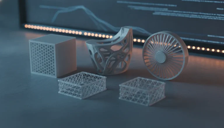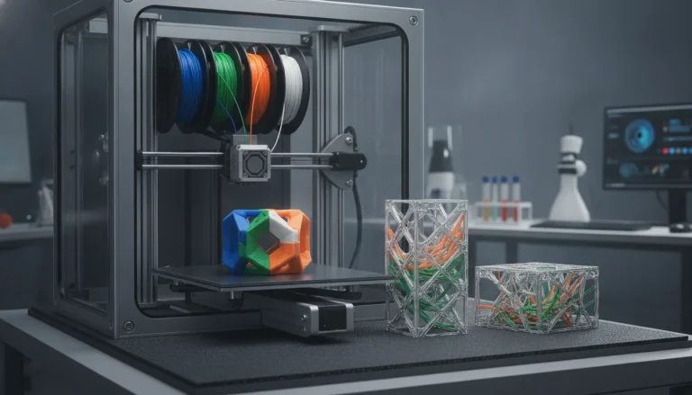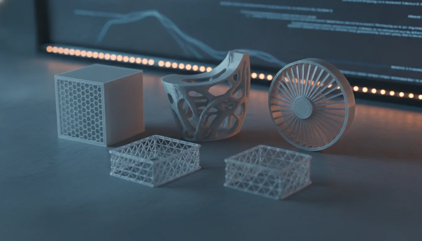
In the realm of 3D printing, the choice of infill pattern often receives less attention than outer shell parameters or material selection. For many common applications, standard infill patterns like rectilinear or grid suffice, providing adequate structural integrity and reasonable print times. However, for demanding scenarios where a part’s performance is paramount, sticking to the defaults can be a significant oversight. This guide delves into the world of advanced infill applications, exploring when and why designers and engineers should consider ditching conventional patterns in favor of more sophisticated solutions that truly enhance a print’s functional characteristics.
Understanding the ‘why’: limitations of standard infill
Standard infill patterns are the workhorses of 3D printing. Rectilinear, grid, and simple honeycomb patterns are widely available in most slicer software and are generally easy to print. They offer a good balance of strength, material usage, and print speed for a vast array of common objects, from decorative pieces to basic tools. Their simplicity makes them predictable and reliable.
- Rectilinear/Grid: Known for decent strength along primary axes and quick printing. However, they can exhibit anisotropic properties, meaning strength varies significantly depending on the direction of applied force.
- Honeycomb: Offers more isotropic strength than rectilinear, but can be slower to print and may still struggle with complex multi-directional loads or specific thermal requirements.
While these patterns are excellent starting points, their limitations become apparent when faced with specific print needs:
- Anisotropic Strength: Many standard infills don’t distribute stress evenly in all directions, leading to weak points under multi-directional loads.
- Suboptimal Weight-to-Strength Ratio: Achieving high strength often requires high infill density, which adds significant weight and material cost.
- Poor Thermal Performance: Standard patterns are not optimized for heat dissipation or insulation, which can be critical for electronic enclosures or parts exposed to varying temperatures.
- Lack of Flexibility Control: For parts requiring specific flexibility or compliance, standard rigid infills are often inadequate.
- Material Waste: Sometimes, a uniform infill density across an entire part is unnecessary, leading to wasted material in less critical areas.
When advanced infill patterns shine: identifying specific print needs
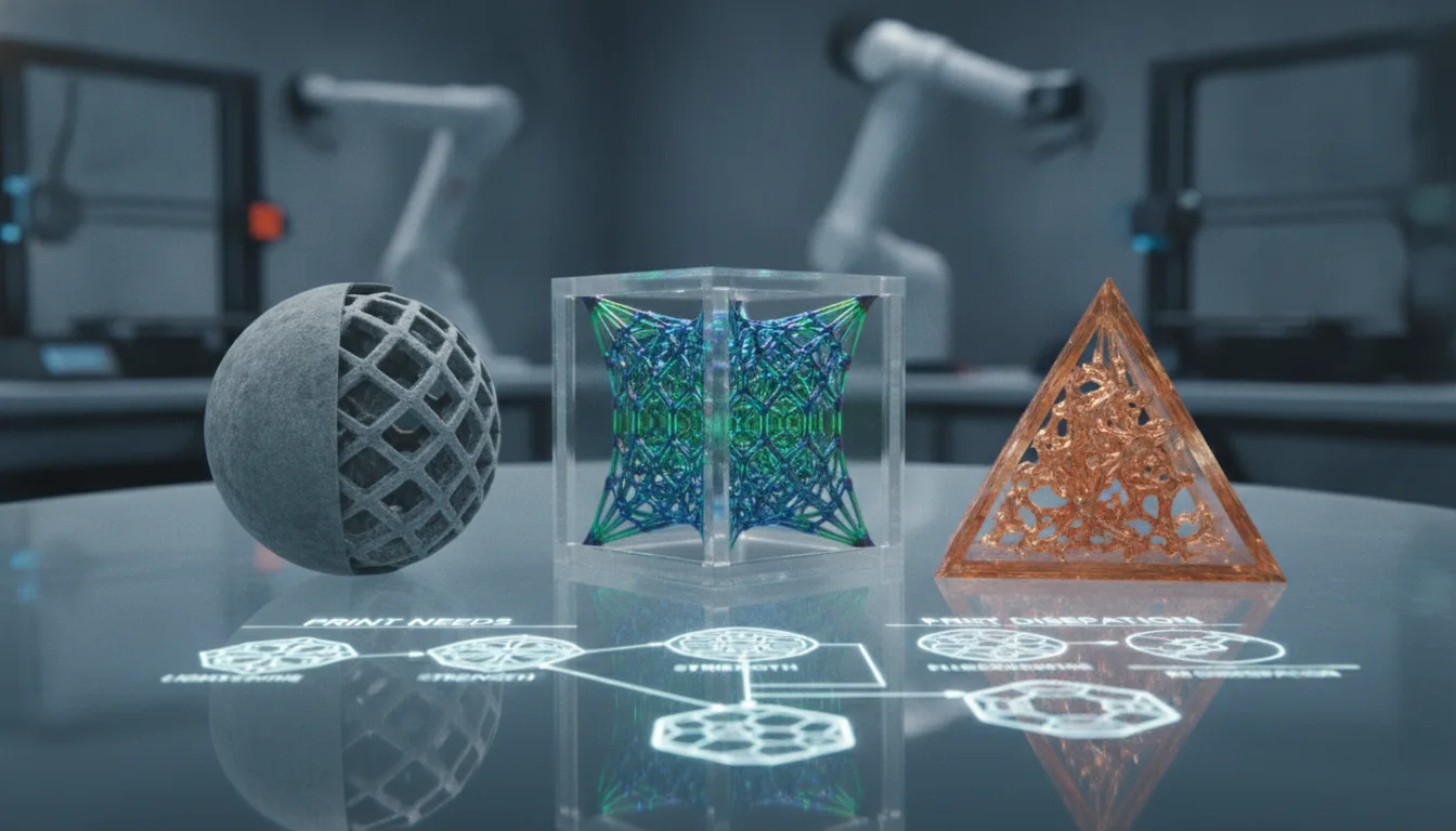
The decision to move to advanced infill patterns is driven by specific functional requirements that standard infills cannot adequately meet. It’s about optimizing performance, material usage, and sometimes even aesthetics for the application at hand. This is where meticulous infill selection truly makes a difference.
Functional prototypes and engineering prints
This category is perhaps the most common driver for exploring advanced infill applications. When a part needs to withstand specific forces, distribute loads, or possess particular mechanical properties, standard infills often fall short. Engineering prints, in particular, demand precision and reliability.
- Optimizing Strength-to-Weight Ratio: For applications in aerospace, robotics, or portable devices, minimizing weight without compromising strength is crucial. Patterns like Gyroid or Cubic Subdivision offer excellent multi-directional strength with less material than a solid print or a dense standard infill. Their complex, interconnected structures distribute stress more effectively.
- Enhanced Impact Resistance: Parts subjected to sudden impacts or vibrations benefit from infills that can absorb and dissipate energy. Concentric infills, for instance, can provide a degree of cushioning, while certain lattice structures can be designed to deform predictably.
- Specific Load Distribution: If a part experiences concentrated loads in particular areas, an Adaptive Infill can be invaluable. This technique allows for higher infill density only where stress is highest, tapering off in less critical zones. This is a prime example of tailoring infill to specific print needs.
- Stiffness and Rigidity: For jigs, fixtures, or structural components, patterns like Octet or Triangles 3D provide superior rigidity across multiple axes compared to 2D patterns.
Thermal management applications
Heat is a significant factor in many mechanical and electronic designs. Advanced infills can play a vital role in managing thermal performance.
- Heat Dissipation: For parts that need to shed heat, such as heatsinks or electronic enclosures, infills with open, interconnected channels (like certain Gyroid variations or custom lattice structures) can facilitate airflow and increase surface area for heat exchange.
- Insulation: Conversely, for parts requiring thermal insulation, infills designed to trap air within small, isolated pockets can be beneficial. Lower density infills with specific cell structures can achieve this, creating a thermal barrier.
Flexible and compliant parts
Creating parts with specific flexibility or spring-like behavior requires careful consideration of infill, especially when using flexible filaments. Standard infills often result in overly stiff or unpredictable deformation.
- Controlled Elasticity: Patterns like Concentric infill, especially with a lower density, can provide predictable flexibility for parts like gaskets, living hinges, or compliant mechanisms. The concentric rings allow for controlled compression and expansion.
- Energy Absorption: For custom damping elements or ergonomic grips, specific lattice structures can be engineered to deform and recover in a desired manner, offering tailored energy absorption characteristics.
Material optimization and cost efficiency
While advanced infills might seem more complex, they often lead to significant material savings and optimized costs in the long run by allowing lower overall infill percentages without sacrificing critical performance. This directly impacts the cost structure of a printed part.
- Reduced Material Usage: By strategically placing material only where needed (e.g., with Adaptive Infill) or by using patterns that achieve high strength with less material (e.g., Gyroid), overall material consumption can be drastically cut.
- Optimized Print Time: While some complex infills can increase print time, the ability to use lower infill percentages overall can sometimes lead to faster prints than a high-density standard infill that achieves similar strength.
A deep dive into advanced infill patterns
Let’s examine some of the most prominent advanced infill patterns and their unique characteristics:
Gyroid
The Gyroid is a fascinating triply periodic minimal surface structure. It’s renowned for its excellent isotropic mechanical properties, meaning it offers uniform strength in all directions. Its continuous, non-intersecting channels also make it ideal for fluid flow applications or as a lightweight structural element. It’s often chosen for functional prototypes requiring balanced strength and for parts where thermal performance is a concern due to its ability to facilitate airflow.
Cubic subdivision / Octet
These patterns are characterized by their strong, interconnected cellular structures. Cubic subdivision offers high stiffness and strength, particularly in load-bearing applications. The Octet infill, a variation often found in professional slicers, provides exceptional strength-to-weight ratios and is particularly suited for high-stress engineering prints where structural integrity is paramount.
Adaptive infill
Adaptive infill is a smart approach where the infill density varies throughout the part based on its geometry and proximity to outer walls. Areas near the outer perimeters or thin sections receive higher infill, while the core of the part can have a lower density. This technique is a game-changer for material optimization, reducing print time, and achieving a good balance between strength and weight, making it highly relevant for various advanced infill applications.
Concentric
While seemingly simple, Concentric infill can be highly effective for specific purposes. It prints concentric lines following the contours of the part’s outer walls. It’s particularly useful for flexible parts, as it allows for controlled deformation. It can also provide excellent support for top layers and improve the strength of thin-walled parts by reinforcing the perimeters.
Honeycomb 3D / Triangles 3D
These are 3D extensions of their 2D counterparts, providing enhanced multi-directional strength compared to their flat versions. By adding a third dimension to the cellular structure, they offer better resistance to forces from various angles, making them suitable for parts that experience complex stress patterns.
Specialized lattice structures
Beyond the standard advanced options, specialized lattice structures represent the pinnacle of infill customization. These are often generated using advanced design software (e.g., nTopology, Autodesk Fusion 360 with generative design) and can be tailored to an almost infinite degree. They are frequently used in highly specialized engineering prints for industries like aerospace, biomedical (e.g., custom implants), or automotive, where specific porosity, energy absorption, or strength characteristics are non-negotiable.
Factors influencing infill selection and cost implications
Choosing the right advanced infill isn’t just about performance; it also involves a careful assessment of practical and economic factors. The cost structure of a 3D printed part is influenced by several variables, and infill choice plays a significant role.
- Print Time: Complex and dense advanced infills inherently increase print time due to more intricate toolpaths and potentially more material extrusion. Longer print times translate directly into higher operational costs, especially in a professional setting where machine utilization is tracked.
- Material Consumption: While advanced infills can optimize material usage for a given strength, certain patterns or high densities will still consume more filament. Material cost is a primary component of overall print cost, so careful balancing is essential. Infill selection directly impacts this.
- Software Capabilities: Utilizing advanced infill patterns often requires sophisticated slicer software or CAD tools with generative design features. The cost of such software licenses or the learning curve associated with them should be factored in.
- Machine Capabilities and Reliability: Printing highly intricate infill patterns demands a well-calibrated and reliable 3D printer. Issues like inconsistent extrusion, poor retraction, or layer adhesion problems can be exacerbated by complex infill geometries, leading to failed prints and wasted material and time.
- Post-processing Requirements: The choice of infill can influence the ease or difficulty of post-processing. For instance, if internal support structures are required within the infill itself (rare, but possible with very complex lattices), their removal can add significant cost and time.
- Iterative Design and Testing: Finding the optimal advanced infill for a critical application often involves a degree of trial and error. The cost of printing multiple prototypes with different infill patterns to validate performance can add up. Utilizing simulation tools like Finite Element Analysis (FEA) can mitigate some of these costs by predicting performance before physical printing.
- Performance vs. Cost Trade-offs: It’s crucial not to simply chase the highest performance without considering the associated costs. A slightly less performant but significantly cheaper infill might be the better choice for a given budget or production volume. The goal is to find the sweet spot where functional requirements are met efficiently.
Making the informed decision: a framework for infill selection
The world’s first desktop full-color 3D & UV printer. Back the Kickstarter campaign with a refundable $50 deposit for VIP pricing.
Navigating the myriad of infill options requires a systematic approach. Here’s a framework to guide your infill selection process for advanced infill applications:
- Define Functional Requirements: Start by clearly articulating what the part needs to do. Is it strength, flexibility, thermal conductivity, weight reduction, or a combination? Quantify these requirements whenever possible (e.g., “must withstand 500N of force in X direction,” “must dissipate 10W of heat”). This is the bedrock for addressing specific print needs.
- Analyze Load Cases and Environmental Factors: Understand the types of forces the part will experience (tension, compression, shear, torsion, impact) and their direction. Consider environmental factors like temperature, humidity, or chemical exposure. This information is critical for engineering prints.
- Evaluate Material Properties: The chosen filament’s properties (tensile strength, elongation at break, heat deflection temperature) will interact with the infill pattern. Some infills perform better with rigid materials, others with flexible ones.
- Assess Manufacturing Constraints: Consider your printer’s capabilities, available software, and your budget for print time and material. These practical constraints will narrow down your viable options.
- Leverage Simulation and Iteration: For critical functional prototypes and engineering prints, utilize simulation tools (like FEA) to predict how different infill patterns will perform under stress. Print test pieces to validate simulations and iterate on your design.
- Balance Performance with Cost: Always weigh the performance gains against the increased print time, material usage, and potential complexity. The most advanced infill isn’t always the most cost-effective solution for every scenario.
Moving beyond standard infill patterns is a strategic decision that can unlock significant performance advantages for 3D printed parts. While standard infills remain perfectly adequate for a wide range of uses, understanding the nuances of advanced infill applications empowers designers and engineers to create parts that truly excel in demanding environments. By carefully considering specific print needs, analyzing the characteristics of various advanced patterns, and weighing the associated cost implications, it’s possible to make informed choices that optimize strength, weight, thermal properties, and overall part functionality, pushing the boundaries of what’s achievable with additive manufacturing.
Frequently asked questions
How do I know if a standard infill is actually failing my part versus just being a bad design?
If your part breaks or deforms unexpectedly, check whether the failure mode aligns with a known standard-infill weakness. For example, a rectilinear infill part that splits along a single axis under a multi-directional load indicates an infill problem, not a design flaw. Print a test coupon with the same outer shell but swap to a Gyroid or adaptive infill; if performance improves noticeably, the original infill was the bottleneck.
Does adaptive infill actually save filament compared to a low-density standard infill?
Yes, adaptive infill saves material by placing higher density only near perimeters and in thin sections, while the core uses a lower percentage. This typically uses less total filament than a uniform 20% rectilinear infill that over-reinforces non-critical interior volume. However, the savings depend on part geometry; a solid block benefits less than a thin-walled shell or a part with variable wall thickness.
Can I use Gyroid infill on any FDM printer, or does it require specific hardware?
Gyroid infill works on any FDM printer that supports the pattern in its slicer (most modern slicers like PrusaSlicer, Cura, and SuperSlicer include it). The printer itself needs no special upgrades, but you must ensure your hotend can maintain consistent extrusion during the pattern’s continuous, non-linear toolpaths. Poorly tuned retraction or a partially clogged nozzle will cause visible defects in Gyroid layers more readily than in rectilinear infill.