In the world of 3D printing, the pursuit of speed often comes at the cost of print quality. Rapid movements can introduce unwanted vibrations, leading to visible artifacts like ‘ghosting’ or ‘ringing’ on your printed parts. This is where Klipper firmware, combined with an ADXL345 accelerometer for input shaping, truly shines. Klipper, a powerful open-source 3D printer firmware, allows for advanced control over your printer’s hardware, pushing it beyond the limitations of traditional firmwares. One of its standout features is input shaping, a sophisticated technique designed to counteract these detrimental vibrations, enabling significantly higher print speeds without sacrificing surface quality. This comprehensive guide will walk you through the process of installing and configuring an ADXL345 accelerometer to unlock Klipper’s full potential, ensuring your prints are both fast and flawless.
Understanding Klipper and input shaping
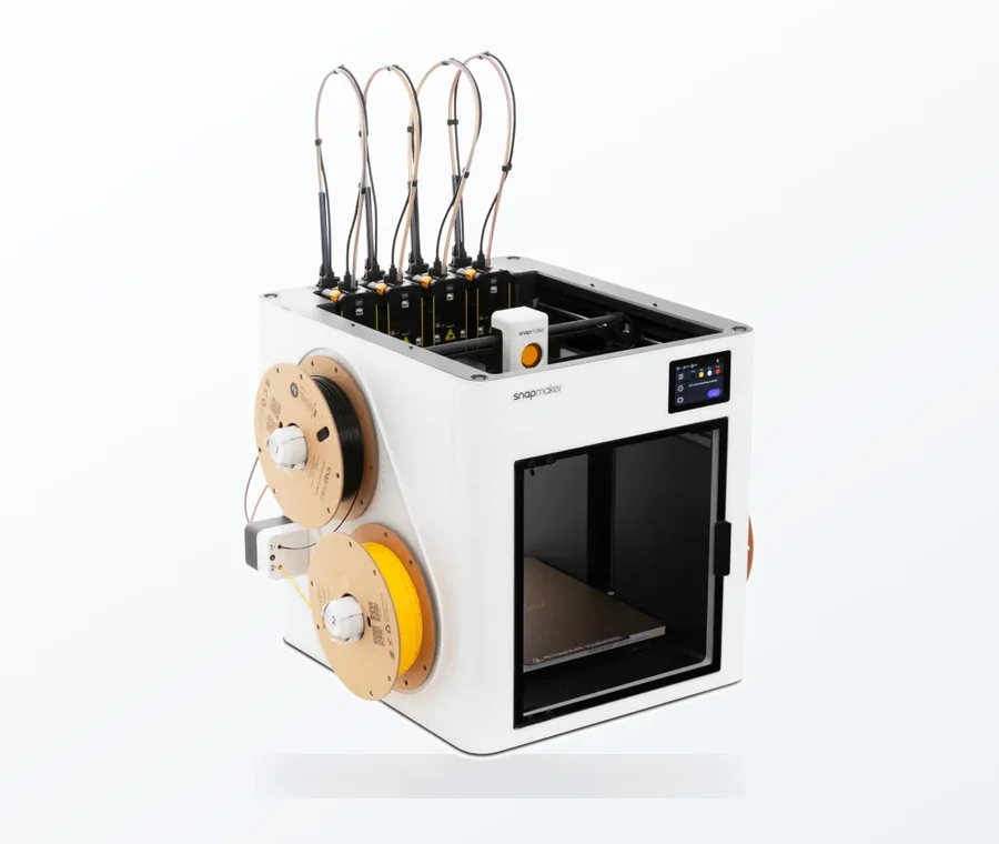
The consumer toolchanger 3D printer: the SnapSwap 4-toolhead system swaps heads in 5 seconds for true multi-color and multi-material printing, with smart calibration and auto filament loading.
- 4 toolheads · 5 s swap
- Up to 500 mm/s · 20,000 mm/s²
- 270 mm cube build volume
- Multi-color & multi-material
Before diving into the installation, it’s crucial to grasp the fundamental concepts behind Klipper and how input shaping works to revolutionize your 3D printing experience.
What is Klipper?
Klipper is a firmware that operates by offloading the complex computational tasks of 3D printing from the printer’s mainboard to a more powerful single-board computer, typically a Raspberry Pi. This architecture allows for more precise motion control, faster processing of G-code commands, and the implementation of advanced features like pressure advance and, critically, input shaping. Unlike traditional firmwares that run entirely on the printer’s microcontroller, Klipper’s host-MCU design provides unparalleled flexibility and computational horsepower, making it a favorite among enthusiasts looking to push the boundaries of their machines.
The problem of resonance and ringing
As 3D printers move at high speeds, particularly during rapid direction changes, the mechanical structure of the printer can vibrate. These vibrations, or resonances, are inherent to any mechanical system and can cause the nozzle to momentarily deflect from its intended path. When these oscillations occur, they translate into visible wavy patterns or echoes on the print’s surface, commonly known as ‘ghosting’ or ‘ringing’. These imperfections are particularly noticeable on prints with sharp corners or intricate details and are a direct impediment to achieving both speed and quality simultaneously. Without proper resonance compensation, increasing print speed inevitably leads to a degradation in print quality.
How input shaping with ADXL345 solves this
Input shaping is a technique that modifies the motion commands sent to the printer’s motors to cancel out these vibrations before they even occur. It works by precisely measuring the resonant frequencies of your printer’s frame, print head, and bed assembly using an accelerometer like the ADXL345. Once these frequencies are known, Klipper applies a pre-calculated counter-movement to the motors, effectively dampening the vibrations. Think of it like a noise-canceling headphone, but for mechanical vibrations. The ADXL345, being a small, affordable, and highly sensitive three-axis accelerometer, is the perfect tool for this job. It allows Klipper to accurately ‘listen’ to your printer’s movements, identify its resonant frequencies, and then apply the necessary firmware modifications to eliminate ringing, paving the way for true high-speed printing without compromise.
Prerequisites for installation

Before embarking on the ADXL345 installation journey, ensure you have the following hardware and software components ready. A little preparation goes a long way in making the process smooth and hassle-free.
Required hardware
- ADXL345 Accelerometer: A small breakout board featuring the ADXL345 chip. These are widely available and inexpensive. Ensure it’s a 3-axis accelerometer.
- Jumper Wires: DuPont style jumper wires (female-to-female or female-to-male, depending on your connections) are essential for wiring the ADXL345.
- Soldering Iron and Solder (Optional but Recommended): For more permanent and reliable connections, especially if connecting directly to a mainboard.
- Mounting Solution: A way to securely attach the ADXL345 to your print head and print bed. This can be a 3D-printed mount, double-sided tape, or zip ties. It needs to be rigid and easily removable/repositionable.
- Raspberry Pi (or similar Klipper host): Your Klipper host machine, already set up and running Klipper.
- 3D Printer: The printer you intend to calibrate.
Software requirements and basic Klipper knowledge
- Klipper Firmware Installed: Your 3D printer should already be running Klipper firmware.
- SSH Access: You should know how to access your Raspberry Pi (or Klipper host) via SSH using tools like PuTTY (Windows) or the terminal (Linux/macOS).
- Basic Linux Command Line Skills: Familiarity with basic commands like ls, cd, nano, and sudo will be helpful.
- Klipper Configuration File (printer.cfg) Access: You’ll need to know how to edit your printer.cfg file, typically through SSH or a web interface like Mainsail/Fluidd.
- Web Interface (Mainsail/Fluidd): These interfaces provide a convenient way to interact with Klipper, monitor your printer, and view calibration graphs.
Step 1: Connecting the ADXL345 accelerometer
The ADXL345 communicates with the Klipper host via the SPI (Serial Peripheral Interface) protocol. There are two primary ways to connect the ADXL345: directly to your Raspberry Pi or to your printer’s mainboard if it supports hardware SPI. Connecting to the Raspberry Pi is generally simpler for most users.
Understanding ADXL345 pinout
A typical ADXL345 breakout board will have the following pins:
- VCC: Power input (usually 3.3V or 5V, check your board’s specifications).
- GND: Ground.
- SCL (SCK): Serial Clock.
- SDA (MOSI): Master Out Slave In.
- SDO (MISO): Master In Slave Out.
- CS (SS): Chip Select / Slave Select.
Connection options: Raspberry Pi vs. direct to mainboard
Connecting to a Raspberry Pi (SPI)
This is the most common and recommended method for most users. The Raspberry Pi has dedicated SPI pins (GPIO pins) that are easy to access.
- VCC: Connect to a 3.3V pin on the Raspberry Pi (e.g., physical pin 1 or 17). Always verify your ADXL345 board’s voltage requirements. While some can handle 5V, 3.3V is safer and compatible with the Pi’s GPIO logic levels.
- GND: Connect to any GND pin on the Raspberry Pi (e.g., physical pin 6, 9, 14, 20, 25, 30, 34, 39).
- SCL (SCK): Connect to the Raspberry Pi’s SCLK (Serial Clock) pin (GPIO11, physical pin 23).
- SDA (MOSI): Connect to the Raspberry Pi’s MOSI (Master Out Slave In) pin (GPIO10, physical pin 19).
- SDO (MISO): Connect to the Raspberry Pi’s MISO (Master In Slave Out) pin (GPIO9, physical pin 21).
- CS (SS): Connect to the Raspberry Pi’s CE0 (Chip Enable 0) pin (GPIO8, physical pin 24).
These connections utilize the Raspberry Pi’s hardware SPI bus. Make sure your jumper wires are securely connected and of good quality. Loose connections can lead to unreliable readings or communication errors.
Connecting to a printer’s mainboard (SPI)
Some advanced mainboards (like certain BigTreeTech boards) offer dedicated SPI headers or pins that can be used to connect the ADXL345 directly to the printer’s microcontroller. This method can sometimes offer slightly lower latency, but it requires more specific knowledge of your mainboard’s pinout and often involves compiling Klipper with specific options enabled for that MCU. Consult your mainboard’s documentation for the correct SPI pins (MISO, MOSI, SCLK, CS) and voltage rails. The principle remains the same: connect VCC, GND, and the four SPI data lines.
Important note on cabling: When connecting the ADXL345, especially if you plan to mount it on the print head, consider the length and flexibility of your wires. Longer wires can introduce electrical noise and make routing more challenging. Use shielded wires if possible, or keep the wires bundled neatly to minimize interference. Ensure the wires are not under tension and do not interfere with the printer’s movement.
Step 2: Configuring Klipper firmware

Once the ADXL345 is physically connected, the next step is to inform Klipper about its presence and how to communicate with it. This involves making edits to your Klipper configuration files, primarily printer.cfg.
Enabling SPI on your Raspberry Pi (if applicable)
If you connected the ADXL345 to your Raspberry Pi, you need to ensure that the SPI interface is enabled. Most Klipper installations have this enabled by default, but it’s good to check:
- SSH into your Raspberry Pi.
- Run the command: sudo raspi-config
- Navigate to ‘3 Interface Options’ -> ‘P4 SPI’ and ensure it’s enabled.
- Reboot your Raspberry Pi if you made any changes.
Modifying your printer.cfg file
Access your printer.cfg file, either via SSH and a text editor like nano or through your Klipper web interface (Mainsail/Fluidd) in the configuration section.
Adding the [adxl345] section
You need to add a section that defines the ADXL345 sensor and its connection pins. The configuration will differ slightly depending on whether you’re using hardware or software SPI, and where the ADXL345 is connected.
For ADXL345 connected to Raspberry Pi hardware SPI:
[adxl345]
cs_pin: raspberry_pi:gpio8
spi_bus: spi0a
Here, gpio8 refers to the Chip Select pin (CE0) on the Raspberry Pi. spi0a specifies the hardware SPI bus. This is the most common and recommended setup for Pi connections.
For ADXL345 connected to Raspberry Pi software SPI (less common, for custom pinouts):
[adxl345]
cs_pin: raspberry_pi:gpioXX # Replace XX with your chosen CS pin
spi_software_miso_pin: raspberry_pi:gpioXX # Replace XX with your chosen MISO pin
spi_software_mosi_pin: raspberry_pi:gpioXX # Replace XX with your chosen MOSI pin
spi_software_sclk_pin: raspberry_pi:gpioXX # Replace XX with your chosen SCLK pin
Only use software SPI if you have a specific reason or are unable to use the hardware SPI pins. This requires you to specify all four SPI pins individually.
For ADXL345 connected to your printer’s mainboard (hardware SPI):
[adxl345]
cs_pin: PA3 # Example: Replace PA3 with your mainboard’s CS pin
spi_bus: spi1 # Example: Replace spi1 with your mainboard’s SPI bus
The exact pin names (e.g., PA3) and SPI bus (e.g., spi1) will depend entirely on your specific mainboard and its Klipper configuration. Refer to your mainboard’s documentation or Klipper’s example configurations for your board.
After adding the [adxl345] section, save and restart Klipper. Check your console for any errors. If Klipper reports ADXL345 not found or similar, double-check your wiring and pin definitions.
Adding the [input_shaper] section
While the ADXL345 section defines the sensor, the [input_shaper] section tells Klipper to enable the input shaping functionality. Initially, you can add an empty section, as the calibration process will fill in the optimal values.
[input_shaper]
# Klipper will automatically recommend shaper_type_x, shaper_freq_x,
# shaper_type_y, and shaper_freq_y after calibration.
# You can add placeholder values for now, but they will be overwritten.
# shaper_type_x: mzv
# shaper_freq_x: 60.0
# shaper_type_y: mzv
# shaper_freq_y: 60.0
Save and restart Klipper again after adding this section.
Verifying your Klipper configuration
After making changes to printer.cfg and restarting Klipper, always check the Klipper console (in Mainsail/Fluidd) for errors. A successful restart without errors indicates that Klipper has parsed your configuration correctly. You can also try sending a simple G-code command like M115 to ensure communication with the printer is still functional.
Step 3: Performing the input shaper calibration
The consumer toolchanger 3D printer: the SnapSwap 4-toolhead system swaps heads in 5 seconds for true multi-color and multi-material printing, with smart calibration and auto filament loading.
With the ADXL345 connected and Klipper configured, it’s time for the exciting part: measuring your printer’s resonances and letting Klipper do its magic. This process involves moving the print head and bed rapidly while the ADXL345 records the vibrations.
Mounting the ADXL345 for X-axis measurement
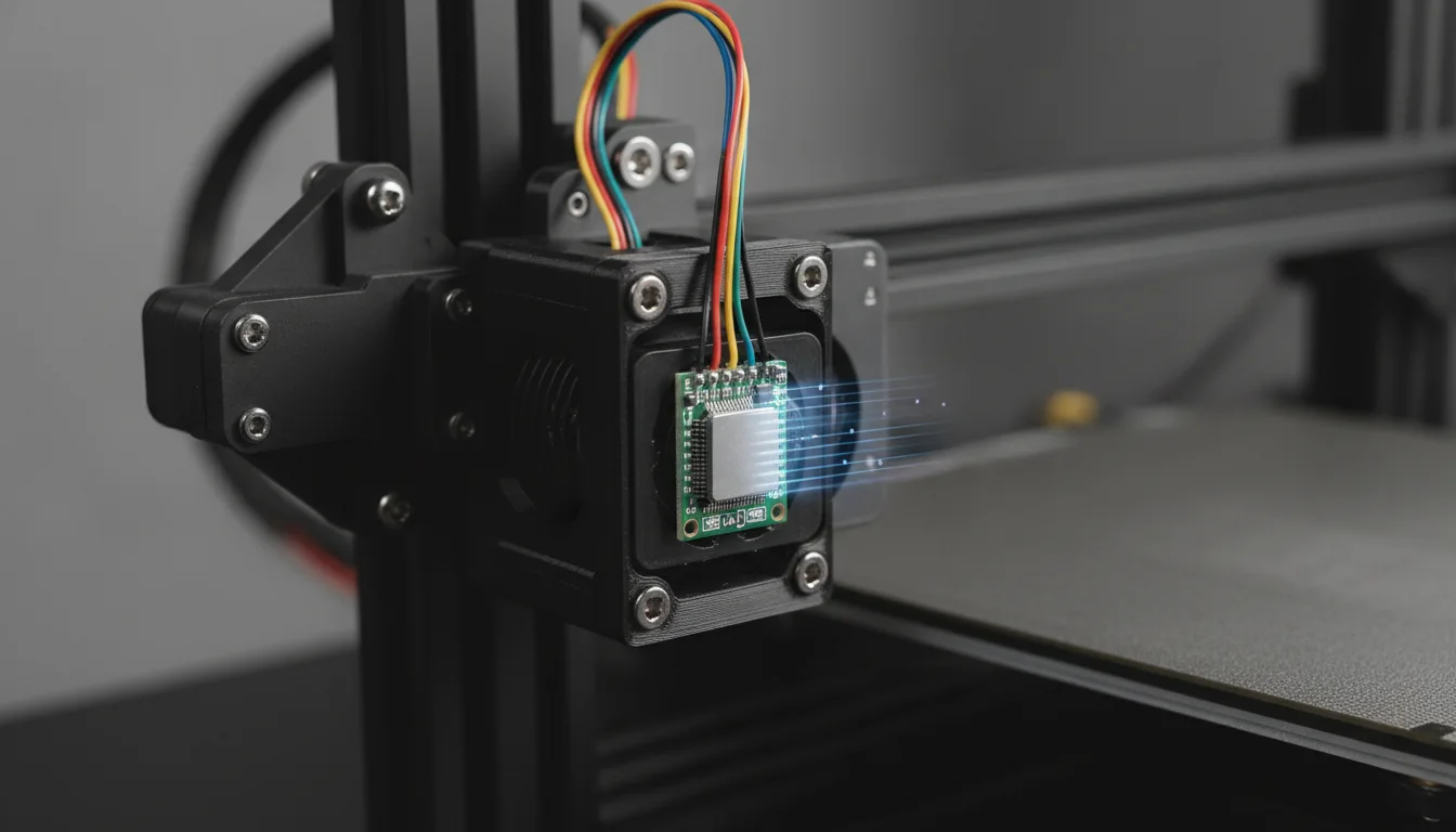
For accurate measurements, the ADXL345 needs to be rigidly mounted to the part of the printer whose vibrations you want to measure. For the X-axis, this means attaching it firmly to your print head (hotend assembly). Ensure the ADXL345 is oriented correctly: the X-axis arrow on the board should align with the printer’s X-axis movement. Use a 3D-printed mount, double-sided tape, or zip ties – whatever ensures a secure, non-wobbly attachment. Any play in the mounting will lead to inaccurate readings.
Running the calibration command for X-axis
Once mounted, navigate to the Klipper console in Mainsail or Fluidd. It’s a good practice to first run MEASURE_AXES_NOISE to get a baseline noise level, though it’s not strictly required for input shaping calibration.
MEASURE_AXES_NOISE
This command helps verify that your ADXL345 is working and not picking up excessive electrical noise. You should see noise levels below 100 for a good setup.
Now, initiate the calibration for the X-axis:
SHAPER_CALIBRATE
Klipper will automatically move your print head back and forth rapidly along the X-axis. Do not touch the printer during this process. It will take a few minutes. Once complete, Klipper will output a recommendation in the console. You’ll also see a link to a graph in your web interface (e.g., http://your-klipper-ip/charts/shaper.html) showing the frequency response and recommended shaper types.
Mounting the ADXL345 for Y-axis measurement
After the X-axis calibration, carefully move the ADXL345 to a rigid part of your print bed. Again, ensure the ADXL345’s Y-axis arrow aligns with the printer’s Y-axis movement. For most beds, mounting it towards the center or a corner of the bed is suitable, as long as it’s firm. If your bed moves in the X-direction (CoreXY, Prusa-style), you would mount it on the bed for X-axis measurement, and on the print head for Y-axis measurement. However, for typical Cartesian and CoreXY printers, X is on the head and Y is on the bed.
Running the calibration command for Y-axis
With the ADXL345 securely mounted on the bed, run the calibration command again:
SHAPER_CALIBRATE
Klipper will now move the print bed (or print head, depending on your printer kinematics) rapidly along the Y-axis. Again, allow it to complete without interruption. You’ll receive another set of recommendations and an updated graph.
Interpreting the results and applying settings
After both X and Y calibrations are complete, Klipper’s console output will provide recommended shaper_type_x, shaper_freq_x, shaper_type_y, and shaper_freq_y values. These are the optimal settings for your specific printer to cancel out its unique resonances.
Example console output:
// … (other output) …
// Recommended shaper_type_x = mzv, shaper_freq_x = 62.4 Hz
// Recommended shaper_type_y = 2hump_ei, shaper_freq_y = 58.7 Hz
// To save these values, add them to your printer.cfg file:
// [input_shaper]
// shaper_type_x: mzv
// shaper_freq_x: 62.4
// shaper_type_y: 2hump_ei
// shaper_freq_y: 58.7
Take these recommended values and update your [input_shaper] section in your printer.cfg file. It’s crucial to use the exact values Klipper recommends.
Updated printer.cfg example:
[input_shaper]
shaper_type_x: mzv
shaper_freq_x: 62.4
shaper_type_y: 2hump_ei
shaper_freq_y: 58.7
Save your printer.cfg file and restart Klipper. Your printer is now configured with input shaping!
Step 4: Verifying and fine-tuning your setup

Configuration is complete, but the real test is in the print. It’s time to see the fruits of your labor and make any necessary adjustments.
Printing a test model
The best way to verify the effectiveness of input shaping is to print a model specifically designed to highlight ringing. Common choices include:
- Input Shaper Test Tower: Many models are available on print repositories that feature sharp corners and flat surfaces to exaggerate ringing.
- Calibration Cube: A simple 20mm calibration cube, especially one with embossed text, can also show improvements.
Print your chosen test model at a speed that previously caused significant ringing. If you were printing at 60mm/s and seeing artifacts, try printing at 80-100mm/s now. The goal is to push the speed to see how well input shaping performs.
Observing print quality and making adjustments
Carefully examine your printed test model. You should observe a significant reduction, if not complete elimination, of ringing and ghosting artifacts. The corners should be sharp, and flat surfaces should be smooth, even at higher print speeds. This marks a successful firmware mod and a huge step towards high-speed printing.
If you still notice some subtle ringing, or if you’re feeling adventurous, you can fine-tune the input shaper settings. Klipper allows you to adjust the shaper_type and shaper_freq slightly. You can also manually test different shaper types (like zv, mzv, ei, 2hump_ei, 3hump_ei) and frequencies around the recommended values. The Klipper documentation provides details on these shaper types. However, for most users, Klipper’s recommended values are an excellent starting point and often the optimal solution.
Remember that input shaping addresses mechanical resonances. Other print quality issues, such as extrusion problems, cooling issues, or stepper motor artifacts, are separate and require different troubleshooting steps. Input shaping focuses purely on the vibrations caused by rapid motion.
Troubleshooting common issues
Even with a detailed guide, hiccups can occur. Here are some common problems and their solutions:
- “ADXL345 not found” error:
- Check Wiring: Double-check all jumper wire connections for continuity and correctness against the pinout. Ensure they are secure.
- Power Supply: Verify the ADXL345 is receiving the correct voltage (3.3V is safest for Pi).
- SPI Enabled: Ensure SPI is enabled on your Raspberry Pi via sudo raspi-config.
- printer.cfg Errors: Carefully review your [adxl345] section in printer.cfg for typos in pin names or bus definitions.
- Faulty ADXL345: In rare cases, the sensor itself might be defective.
- Inaccurate measurements / erratic graphs:
- Loose Mounting: The ADXL345 must be rigidly mounted. Any wobble will introduce false readings.
- Electrical Noise: Long or unshielded wires can pick up electrical noise. Try shorter wires, or route them away from motor cables.
- Power Fluctuations: Ensure a stable power supply to both the Raspberry Pi and the ADXL345.
- Ringing still present after calibration:
- Rethink Mounting: Ensure the ADXL345 was mounted in the correct orientation and on the correct moving part for each axis.
- Kinematics Check: Verify your printer’s kinematics are correctly configured in Klipper.
- Mechanical Issues: Input shaping cannot fix underlying mechanical problems like loose belts, wobbly gantries, or worn bearings. Address these first.
- Re-calibrate: Sometimes a re-calibration can yield better results, especially if the printer’s mechanics have changed or settled.
Conclusion: Embrace high-speed, high-quality printing

Implementing Klipper’s input shaper with an ADXL345 accelerometer is one of the most impactful upgrades you can make to your 3D printer. This firmware mod directly addresses the age-old dilemma of speed versus quality, allowing you to push your machine to its limits without the unsightly artifacts of ringing and ghosting. By following this practical guide, you’ve not only configured a piece of hardware but also unlocked a new realm of possibilities for your 3D printing endeavors. Say goodbye to slow prints and hello to crisp, clean, high-speed printing. The precise resonance compensation offered by this setup means your projects will not only finish faster but will also boast a professional finish, truly leveraging Klipper’s full potential. Happy printing!
Frequently asked questions
Do I need to re-run the calibration if I change my printer’s hardware or print speed?
Yes. Any modification that changes your printer’s mechanical stiffness or mass distribution—such as swapping the hotend, adding a heavier print bed, or tightening belts—will shift its resonant frequencies. You should remount the ADXL345 and run SHAPER_CALIBRATE again to obtain new shaper_type and shaper_freq values. Input shaping compensates for the printer’s current mechanical resonance, so recalibration is required after any significant hardware change.
Can I leave the ADXL345 permanently attached to my printer?
Yes, you can leave it connected and mounted, but it is not required for normal printing once calibration is complete. Klipper applies the saved shaper settings from the [input_shaper] section of printer.cfg whether or not the ADXL345 is still attached. Many users remove the accelerometer to avoid cable drag or accidental snags, while others leave it in place for periodic re-checks. If you remove it, simply disconnect the jumper wires or unplug the board; no configuration changes are needed.
What should I do if the SHAPER_CALIBRATE command causes my printer to make loud noises or shake violently?
This is normal during calibration. Klipper deliberately drives the print head and bed at high acceleration across a range of frequencies to excite the printer’s resonances. The motion is safe for properly assembled printers, but if you have loose components, belts, or hardware, the shaking can worsen. Stop the calibration immediately, tighten any loose mechanical parts, ensure your printer is on a stable surface, and then retry. If the noise is excessive, you can reduce the maximum acceleration in your printer.cfg temporarily before running SHAPER_CALIBRATE again.