In the world of 3D printing, speed and quality often feel like a zero-sum game. Push for faster prints, and you often compromise on surface finish, leading to ghosting, ringing, or other artifacts. However, with Klipper firmware and its powerful input shaping capabilities, powered by an ADXL345 accelerometer, this compromise becomes a relic of the past. This guide will walk you through the process of harnessing Klipper for speed, integrating the ADXL345, and mastering input shaping to achieve truly blazing fast prints without sacrificing an ounce of quality.
Understanding Klipper, input shaping, and the ADXL345
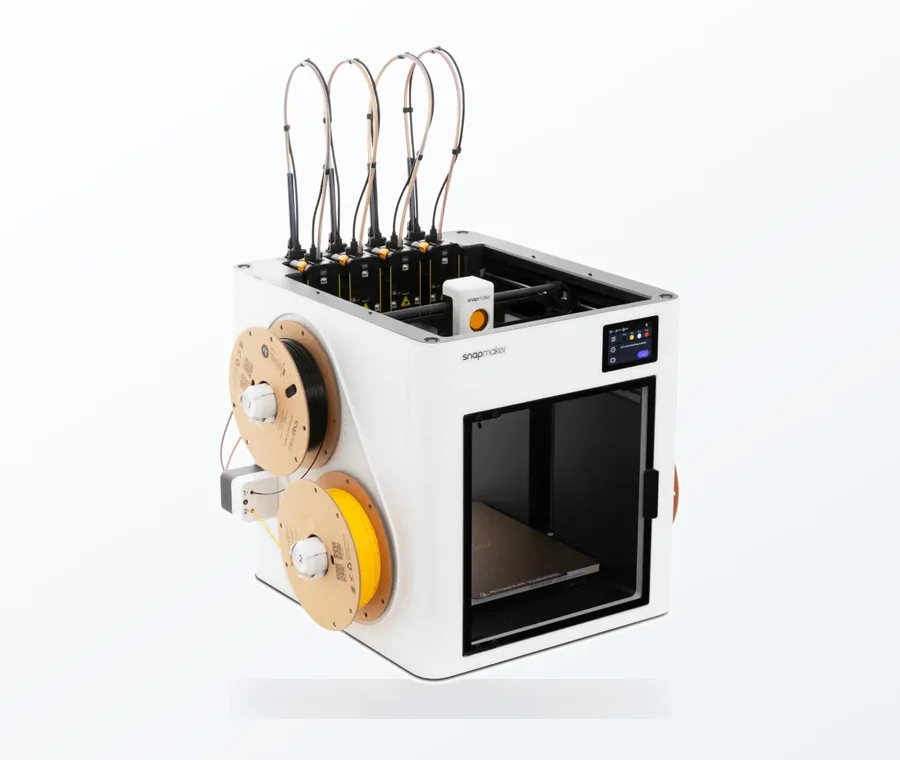
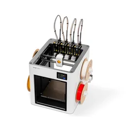
The consumer toolchanger 3D printer: the SnapSwap 4-toolhead system swaps heads in 5 seconds for true multi-color and multi-material printing, with smart calibration and auto filament loading.
- 4 toolheads · 5 s swap
- Up to 500 mm/s · 20,000 mm/s²
- 270 mm cube build volume
- Multi-color & multi-material
Before diving into the technicalities, let’s briefly understand the core components that make high-speed Klipper tuning possible.
What is Klipper?
Klipper is an open-source 3D printer firmware that leverages the processing power of a single-board computer (SBC) like a Raspberry Pi to offload complex calculations from your printer’s main microcontroller unit (MCU). This architectural shift allows for more precise motion control, higher step rates, and advanced features that traditional firmware often struggles with. Its modular design and Python-based configuration make it incredibly flexible and powerful for those looking to push the boundaries of their 3D printer’s performance.
The necessity of input shaping for speed
As print speeds increase, the rapid acceleration and deceleration of the print head can induce vibrations in the printer’s frame and moving parts. These vibrations, known as resonances, manifest as visible artifacts on your prints, such as ghosting (ringing) or salmon skin. Input shaping is a technique designed to counteract these resonances. By strategically altering the motion commands sent to the stepper motors, Klipper can essentially ‘cancel out’ the printer’s natural vibrations, allowing for much higher accelerations and speeds without quality degradation. This is a cornerstone of high-speed Klipper tuning.
The role of the ADXL345 accelerometer
To effectively apply input shaping, Klipper needs to know the specific resonant frequencies of your printer’s axes. This is where the ADXL345 comes in. The ADXL345 is a small, inexpensive 3-axis accelerometer that can be temporarily mounted to your print head or bed. Klipper uses this sensor to measure the vibrations generated during controlled test movements, identifying the exact frequencies at which your printer resonates. This data is then used to calculate and apply the optimal input shaper settings, making the ADXL345 setup guide an essential step in your Klipper firmware optimization journey.
Getting started: Prerequisites for Klipper firmware optimization

Before you begin, ensure you have the following:
- A Klipper-enabled 3D printer: Your printer should already be running Klipper firmware on an SBC (e.g., Raspberry Pi) connected to your printer’s MCU.
- ADXL345 accelerometer: Available from various online retailers.
- Wiring: Jumper wires (Dupont connectors) to connect the ADXL345 to your Raspberry Pi or MCU.
- Mounting solution: A small 3D printed mount for the ADXL345 to attach it securely to your print head and, ideally, your print bed.
- SSH access: To your Raspberry Pi (e.g., using PuTTY or the terminal on Linux/macOS).
- Basic understanding of Klipper configuration: Familiarity with editing your printer.cfg file.
Step-by-step guide: ADXL345 integration and input shaping
Let’s dive into the practical steps for ADXL345 setup guide and input shaping 3D printer optimization.
1. Wiring the ADXL345
The ADXL345 typically communicates via SPI (Serial Peripheral Interface). The most common method is to connect it directly to your Raspberry Pi’s GPIO pins. However, some users prefer to connect it to their printer’s MCU if it has available SPI pins, especially for multi-toolhead setups or specific MCU architectures. For simplicity, we’ll focus on connecting to the Raspberry Pi.
Connecting to Raspberry Pi GPIO:
Locate the SPI pins on your Raspberry Pi’s GPIO header. They are typically:
- VCC (3.3V): Connect to Raspberry Pi’s 3.3V pin (Pin 1 or 17).
- GND: Connect to Raspberry Pi’s GND pin (Pin 6, 9, 14, 20, 25, 30, 34, 39).
- SDA (SDI/MOSI): Connect to Raspberry Pi’s MOSI (GPIO10 / Pin 19).
- SDO (MISO): Connect to Raspberry Pi’s MISO (GPIO9 / Pin 21).
- SCL (SCK): Connect to Raspberry Pi’s SCLK (GPIO11 / Pin 23).
- CS (Chip Select): Connect to Raspberry Pi’s CE0 (GPIO8 / Pin 24).
Important: Always double-check your Raspberry Pi’s pinout diagram for accuracy. Ensure your ADXL345 is compatible with 3.3V logic; most are, but some older modules might require level shifters if they’re 5V.
2. Configuring Klipper for ADXL345
Once wired, you need to tell Klipper how to communicate with the ADXL345. SSH into your Raspberry Pi and edit your printer.cfg file.
Enable SPI on your Raspberry Pi:
If you haven’t already, enable SPI on your Raspberry Pi. Run sudo raspi-config, navigate to ‘Interface Options’, then ‘SPI’, and enable it. Reboot your Pi afterwards.
Add the ADXL345 configuration to printer.cfg:
Open your printer.cfg file (e.g., nano ~/klipper_config/printer.cfg) and add the following sections:
[adxl345]
cs_pin: rpi:gpio8
spi_software_sclk_pin: rpi:gpio11
spi_software_mosi_pin: rpi:gpio10
spi_software_miso_pin: rpi:gpio9
[resonance_tester]
accel_chip: adxl345
probe_points: 100,100,20 ; Adjust X, Y, Z to a point near the center of your bed
- cs_pin: This is the Chip Select pin. rpi:gpio8 refers to GPIO8 on the Raspberry Pi.
- spi_software_sclk_pin, spi_software_mosi_pin, spi_software_miso_pin: These define the software SPI pins. Ensure these match your wiring.
- [resonance_tester]: This section enables the resonance testing feature.
- accel_chip: adxl345: Specifies that we’re using an ADXL345.
- probe_points: This is the X, Y, Z coordinate where the resonance test will be performed. Choose a point near the center of your bed. The Z height should be low enough to prevent issues but high enough to clear the bed.
Save and restart Klipper (firmware_restart command in your Klipper interface or sudo service klipper restart via SSH).
3. Running the resonance test
Now that Klipper is configured, it’s time to measure your printer’s resonances. Ensure the ADXL345 is securely mounted to your print head.
Install the Klipper analysis scripts:
If you haven’t already, you’ll need the Klipper scripts to analyze the ADXL345 data. SSH into your Pi and run:
cd ~/klipper/scripts
sudo apt update
sudo apt install python3-numpy python3-matplotlib
Execute the resonance test commands:
In your Klipper interface (Fluidd/Mainsail console), run the following commands:
TEST_RESONANCES AXIS=X
TEST_RESONANCES AXIS=Y
Klipper will move your print head rapidly along each axis, measuring vibrations with the ADXL345. This process takes a few minutes per axis. You’ll see output in the console indicating the progress. The results will be saved as CSV files in the /tmp/ directory on your Raspberry Pi (e.g., /tmp/resonances_x_*.csv).
Note on mounting: For accurate results, it’s crucial to mount the ADXL345 rigidly. For X-axis testing, mount it to the print head. For Y-axis testing, it’s often best to mount it to the print bed to capture bed resonances effectively. If you’re testing both, you might need to remount the ADXL345 and run the Y-axis test separately.
4. Analyzing results and implementing input shaping
With the resonance data collected, the next step is to analyze it and apply the recommended input shaper settings.
Generate the resonance graphs and recommended shapers:
SSH into your Pi and navigate to the Klipper scripts directory:
cd ~/klipper/scripts
Then, run the calibration script:
python3 calibrate_shaper.py /tmp/resonances_x_*.csv -o /tmp/shaper_calibrate_x.png
python3 calibrate_shaper.py /tmp/resonances_y_*.csv -o /tmp/shaper_calibrate_y.png
This will output recommended shaper types and frequencies in the terminal for both X and Y axes. It will also generate PNG graphs (shaper_calibrate_x.png and shaper_calibrate_y.png) that you can view to understand your printer’s resonance profile. You can download these images using an SFTP client (like WinSCP) to visualize them.
Interpreting the output:
The script will recommend an input shaper type (e.g., mzv, 2hump_ei, 3hump_ei) and a frequency for each axis. For example, you might see something like:
Recommended shaper for X axis:
shaper_type: mzv
frequency: 50.4 Hz
Recommended shaper for Y axis:
shaper_type: 2hump_ei
frequency: 42.1 Hz
Apply input shaping to printer.cfg:
Edit your printer.cfg file again and add or modify the [input_shaper] section with the recommended values:
[input_shaper]
shaper_type_x: mzv
shaper_freq_x: 50.4
shaper_type_y: 2hump_ei
shaper_freq_y: 42.1
# You can also set a default acceleration if you haven’t already
# max_accel: 5000
# max_accel_x: 5000
# max_accel_y: 5000
Save and restart Klipper.
5. Verifying and fine-tuning
With input shaping enabled, it’s time to verify the improvements. This is where your high-speed Klipper tuning truly comes to fruition.
Print a resonance test tower:
There are many models available online for resonance test towers (e.g., from Teaching Tech or other Klipper communities). These towers are designed to print at increasing speeds or accelerations, allowing you to visually inspect how well input shaping has eliminated artifacts. Print one of these towers at a higher acceleration than you normally would (e.g., start at 3000 mm/s² and increase to 5000 or 8000 mm/s²).
Observe print quality:
Compare the test tower to previous prints without input shaping. You should see a dramatic reduction or complete elimination of ghosting and ringing. If you still observe minor artifacts, you can try slightly tweaking the shaper_freq values (e.g., +/- 1-2 Hz) or experimenting with different shaper types if the script offered alternatives, though the recommended ones are usually spot on.
Advanced considerations and troubleshooting resonance compensation

- Rigid mounting: The ADXL345 must be mounted very rigidly to the part you are measuring. Any wobbling or loose connections will lead to inaccurate readings. Use screws, not just tape.
- Measuring both axes: While mounting to the print head for X and the bed for Y is common, some printers might benefit from measuring both axes from the print head. Experiment to find what works best for your specific setup.
- Multiple ADXL345s: For advanced users or complex setups, Klipper supports multiple ADXL345 sensors, allowing you to measure different parts of the printer simultaneously.
- Environmental factors: Ensure your printer is on a stable surface. Vibrations from your desk or workbench can interfere with resonance testing.
- Troubleshooting connection issues: If Klipper reports an error connecting to the ADXL345, double-check your wiring, ensure SPI is enabled on the Pi, and verify the cs_pin and spi_software_*_pin settings in printer.cfg.
- Understanding the graphs: The generated graphs show the frequency response of your printer. Peaks indicate resonant frequencies. The input shaper aims to flatten these peaks. Learning to read these graphs can help in advanced resonance compensation.
- Impact on print quality: Beyond just speed, effective input shaping also contributes to overall print quality, making features sharper and surfaces smoother even at moderate speeds.
Conclusion
The consumer toolchanger 3D printer: the SnapSwap 4-toolhead system swaps heads in 5 seconds for true multi-color and multi-material printing, with smart calibration and auto filament loading.
Klipper firmware optimization, especially through ADXL345 integration and input shaping, is a game-changer for 3D printer performance. It unlocks the true potential of your hardware, allowing you to print at speeds previously thought impossible without compromising on the quality of your finished parts. By following this ADXL345 setup guide and embracing the power of resonance compensation, you’re not just making your printer faster; you’re making it smarter and more efficient. So, take the plunge, dial in those shapers, and enjoy the satisfaction of watching your printer churn out stunning prints at blazing speeds.
Frequently asked questions
Do I need to rerun the resonance test if I change my printer’s hardware or mounting surface?
Yes. Any change that alters the printer’s mechanical resonance—such as swapping the hotend, adding a heavier print head, moving the printer to a different desk, or tightening the frame—can shift the resonant frequencies. You should remount the ADXL345 and run TEST_RESONANCES again for both axes to generate fresh shaper recommendations, then update your printer.cfg with the new values.
Can I leave the ADXL345 permanently attached to the print head?
Yes, you can leave it wired and mounted, but it adds a small amount of mass to the print head (roughly 3–5 grams for the sensor and mount). For most printers this has negligible effect on speed or quality, but on very lightweight or high-speed printers you may prefer to remove it after tuning. If you leave it attached, ensure the wiring is secured so it cannot snag on the print or frame.
What should I do if the resonance test fails with a “No connection to ADXL345” error?
First confirm SPI is enabled on your Raspberry Pi via sudo raspi-config and reboot. Then double-check your wiring: VCC must go to 3.3V (not 5V), and each SPI pin must match the cs_pin, spi_software_sclk_pin, spi_software_mosi_pin, and spi_software_miso_pin entries in your printer.cfg. A common mistake is swapping MOSI and MISO or using the wrong chip-select pin. If the wiring is correct, try a different ADXL345 module, as some low-cost units arrive defective.