Stepping into the world of 3D modeling can feel like learning a new language, especially when terms like 'parametric' start popping up. But fear not! Parametric modeling for beginners isn't as daunting as it sounds. In fact, it's a game-changer that empowers you to create flexible, adaptable designs. Imagine designing a shelf today, only to realize tomorrow you need it wider, taller, or with more shelves. Without parametric modeling, you'd often be starting from scratch. With it, a few clicks can update your entire design.
This tutorial will guide you through building your very first resizable model: a simple, adjustable shelf design. We'll break down the core concepts, walk through the practical steps, and highlight why this approach is invaluable for anyone venturing into 3D design. By the end, you'll not only have a functional model but also a solid understanding of how to create an adjustable design that can evolve with your needs.
Understanding the core concepts of parametric modeling

Before we dive into the actual modeling, let's get a handle on what makes parametric modeling tick. At its heart, it's about defining your model not just by fixed dimensions, but by relationships and rules that govern its geometry.
What are basic parameters?
Think of parameters as variables that control your design. These can be:
- Dimensions: Length, width, height, radius, angle. Instead of typing "100mm," you might define a parameter called
shelf_widthand assign it a value. - Counts: Number of shelves, number of holes.
- Formulas: Parameters can be linked to each other. For instance,
shelf_spacing = (shelf_height - (num_shelves * shelf_thickness)) / (num_shelves + 1). - Material properties: Though less common in basic geometry, some advanced systems allow material properties to be parameters.
The magic happens when you change the value of a parameter; the entire model, and any features linked to that parameter, automatically update.
The power of relationships and constraints
Beyond simple dimensions, parametric modeling relies heavily on relationships and constraints. These are rules that dictate how geometric elements interact with each other. Common examples include:
- Geometric Constraints: Coincident (two points share the same location), parallel, perpendicular, tangent, horizontal, vertical.
- Dimensional Constraints: Directly linking a dimension to a parameter or a fixed value.
- Assembly Constraints: How different components fit together (e.g., aligning faces, concentric axes).
By defining these relationships, you create an intelligent model that maintains its design intent even when its underlying dimensions change. This is crucial for an adjustable design.
Choosing your tool (and why the principles are universal)
While this tutorial won't delve into a direct comparison of software costs, it's worth noting that the principles of parametric modeling are universal across many CAD (Computer-Aided Design) programs. Popular choices for beginners and professionals alike include:
- Fusion 360: A cloud-based solution often free for hobbyists and startups.
- Onshape: Another cloud-native platform, excellent for collaborative work.
- FreeCAD: An open-source, free option with a steep learning curve but powerful capabilities.
- SolidWorks, Inventor, CATIA: Industry-standard professional tools with robust parametric features.
For this 3D modeling tutorial, we'll focus on the conceptual steps that apply regardless of your chosen software. The exact button names might differ, but the logic remains consistent.
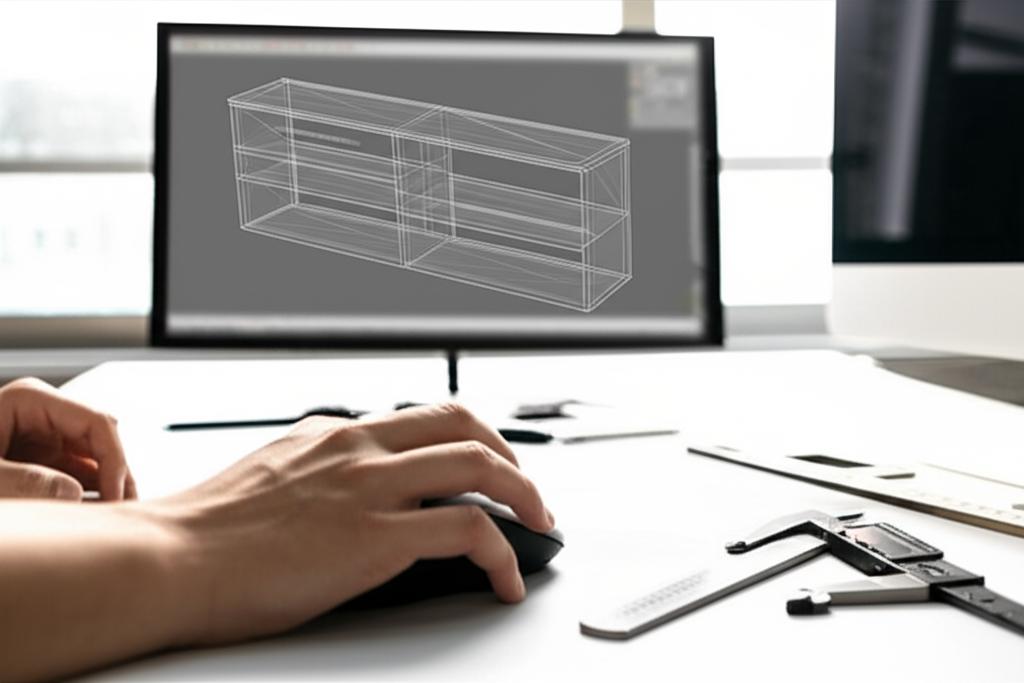
Step-by-step tutorial: Building a resizable shelf design

Explore the
Snapmaker U1
Let's roll up our sleeves and build that shelf! Our goal is to create a model where we can easily change the overall width, height, depth, shelf thickness, and number of shelves.
Step 1: Planning your shelf and identifying key parameters
Before touching any software, sketch out your idea. What are the essential dimensions you'll want to control? For our shelf, these are:
overall_widthoverall_heightoverall_depthshelf_thickness(for all panels: sides, top, bottom, and internal shelves)num_shelves(the number of internal shelves, not including top/bottom)
Having these in mind will make the next step much smoother.
Step 2: Setting up your software environment and defining parameters
Open your chosen CAD software and create a new document. The first thing you'll want to do is define your user parameters. Most software has a dedicated 'Parameters' or 'Variables' dialog.
- Create New Parameters: For each item identified in Step 1, create a new parameter.
- Assign Initial Values: Give them reasonable starting values. For example:
overall_width= 800 mmoverall_height= 1200 mmoverall_depth= 300 mmshelf_thickness= 18 mmnum_shelves= 3 (this will be an integer type)
These are your basic parameters, the levers you'll pull to adjust your design.
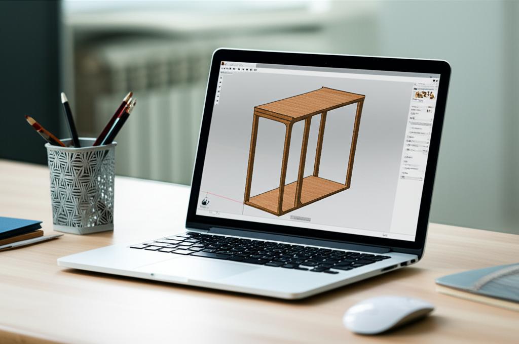
Step 3: Sketching the base profile (side panel)
We'll start by creating one of the vertical side panels of the shelf. This is usually done by sketching a 2D profile and then extruding it into 3D.
- Start a New Sketch: Select a suitable plane (e.g., the XY or front plane).
- Draw a Rectangle: Use the rectangle tool to draw a simple rectangle. Don't worry about exact dimensions yet.
- Apply Dimensional Constraints:
- Constrain the height of the rectangle to
overall_height. - Constrain the width of the rectangle to
overall_depth.
- Constrain the height of the rectangle to
- Position the Sketch (Optional but good practice): You might want to constrain one corner to the origin (0,0,0) or center the sketch for easier future operations.
Your sketch should now be fully defined, meaning it turns a specific color (often black or dark blue) indicating all its dimensions and positions are fixed by parameters or constraints.
Step 4: Extruding the side panel
Now, let's give our 2D sketch some thickness.
- Exit the Sketch: Finish the sketch environment.
- Select the Extrude Tool: Choose the profile you just created.
- Set Extrusion Distance: Instead of a fixed number, set the extrusion distance to
shelf_thickness.
You now have your first 3D body – a side panel whose height, depth, and thickness are all controlled by your parameters.
Step 5: Creating the top and bottom panels
Next, we'll create the horizontal top and bottom panels.
- Create a New Sketch: Choose a plane suitable for the top/bottom panel (e.g., on top of the side panel or a parallel plane).
- Draw a Rectangle:
- Constrain the length of the rectangle to
overall_width. - Constrain the width of the rectangle to
overall_depth.
- Constrain the length of the rectangle to
- Extrude: Extrude this profile by
shelf_thickness. - Position: Use assembly or move tools to position this panel correctly. For the bottom panel, it should be flush with the bottom of the side panel. For the top, flush with the top. Remember to link these positions parametrically if your software allows, or ensure they are properly constrained.
Repeat this for both the top and bottom panels. You might even be able to create one and then pattern or mirror it depending on your software.
Step 6: Adding shelves and spacing parametrically
This is where the true power of an adjustable design comes into play.
- Create a Single Shelf Profile:
- Start a new sketch on a suitable plane.
- Draw a rectangle.
- Constrain its length to
overall_width - (2 * shelf_thickness)(accounting for the two side panels). - Constrain its width to
overall_depth.
- Extrude the Shelf: Extrude this profile by
shelf_thickness. - Position the First Shelf: Place this first internal shelf at a specific distance from the bottom. You could define a parameter like
bottom_shelf_offsetor calculate it. - Create a Linear Pattern: Most CAD software has a 'Linear Pattern' or 'Rectangular Array' feature. This allows you to duplicate a feature or body multiple times along a direction.
- Select the Body/Feature: Choose the single shelf you just created.
- Select Direction: Choose a vertical edge or axis.
- Set Quantity: Set this to
num_shelves. - Set Spacing/Distance: This is critical. You'll need a formula to evenly distribute the shelves. A common approach is:
(overall_height - (2 * shelf_thickness) - (num_shelves * shelf_thickness)) / (num_shelves + 1). This calculates the available vertical space, subtracts the thickness of all internal shelves, and then divides by the number of gaps (which isnum_shelves + 1). Make sure your software's pattern tool allows for expressions here.
Now, if you change num_shelves, your model will automatically add or remove shelves, and their spacing will adjust proportionally!
Step 7: Adding joinery (optional but illustrative)
For a truly robust resizable model, even joinery can be parametric. For example, if you wanted to add dados (grooves) for your shelves:
- Sketch a Dado Profile: On the inner face of a side panel, sketch a rectangle for a dado.
- Constrain Dimensions: Set its width to
shelf_thicknessand its depth to a new parameter, e.g.,dado_depth. - Position Parametrically: Crucially, constrain its vertical position to the corresponding shelf. This often involves relating the dado's top/bottom edge to the shelf's top/bottom edge with a coincident or offset constraint.
- Extrude Cut: Use an 'Extrude Cut' or 'Remove Material' operation.
- Pattern the Dado: Just like with the shelves, use a linear pattern to duplicate this dado cut for all shelves, ensuring it follows the same spacing logic.
This level of detail ensures that if you change shelf_thickness, your dados automatically resize, and if you change num_shelves, new dados appear or disappear with the shelves.
Step 8: Testing and modifying your parametric model
The moment of truth! Go back to your 'Parameters' dialog.
- Change a Parameter: Try changing
overall_width, thenoverall_height, thennum_shelves. - Observe the Update: Your model should automatically regenerate, reflecting the new values while maintaining all the design relationships you've set up.
- Troubleshooting: If something breaks (e.g., features fail, errors appear), it usually means a constraint isn't fully defined or there's a conflict. Go back through your steps, focusing on sketches and feature definitions. Look for under-constrained (too flexible) or over-constrained (conflicting rules) elements.
This iterative testing is key to ensuring your adjustable design is truly robust.
Advantages of parametric modeling for beginners
For those just starting out, embracing parametric modeling offers significant advantages that can save you time, reduce frustration, and open up new design possibilities. While we're not comparing specific software costs, the inherent flexibility of parametric features provides immense value:
- Rapid Iteration: Quickly explore different design variations by simply changing parameter values. This allows for faster prototyping and design refinement, reducing the 'cost' of design changes.
- Reduced Errors: When a change is made, the entire model updates consistently, minimizing the chance of manual errors that often occur when updating fixed-dimension models.
- Design Scalability: Easily adapt a single design to different sizes or configurations without having to redraw everything. This is perfect for product lines or custom orders.
- Foundation for Advanced Work: Parametric thinking is fundamental to more complex 3D modeling tasks, including assemblies, simulations, and advanced manufacturing. Mastering it early on sets you up for success.
- Clarity of Design Intent: Parameters and relationships clearly document how your design is intended to function, making it easier for others (or your future self) to understand and modify.
This approach transforms your 3D models from static representations into dynamic, intelligent objects, offering a distinct advantage over traditional, fixed-dimension modeling methods in terms of efficiency and adaptability.
Common pitfalls and tips for success
Even with the best intentions, you might run into some bumps. Here are some tips:
- Start Simple: Don't try to make everything parametric at once. Master the basics with simple models like our shelf.
- Plan Your Parameters: Before you even start sketching, list out the key dimensions you want to control.
- Use Clear Parameter Names:
shelf_widthis much better thand1. It makes your model easier to understand and modify later. - Test Frequently: After adding a major feature or parameter, try changing a few values to see if the model updates as expected.
- Understand Parent-Child Relationships: Features are often built upon previous ones. If you delete or modify a 'parent' feature, its 'children' might break.
- Avoid Over-Constraining: Don't add redundant dimensions or constraints. If a dimension is already defined by parameters or other constraints, adding another can create conflicts.
Conclusion
You've just completed your first foray into parametric modeling for beginners! By building a resizable model like this shelf, you've grasped the fundamental concepts of parameters, relationships, and the immense power they bring to 3D design. This 3D modeling tutorial has equipped you with the knowledge to create truly adjustable designs that are efficient, flexible, and ready to adapt to any challenge.
Parametric modeling isn't just about making changes; it's about designing with foresight and creating intelligent models that save time and effort in the long run. Keep practicing, experiment with different parameters, and soon you'll be tackling even more complex adjustable designs with confidence. Happy modeling!
