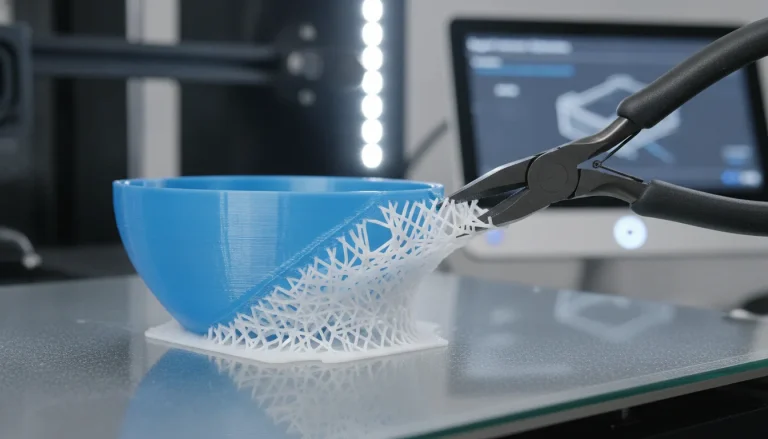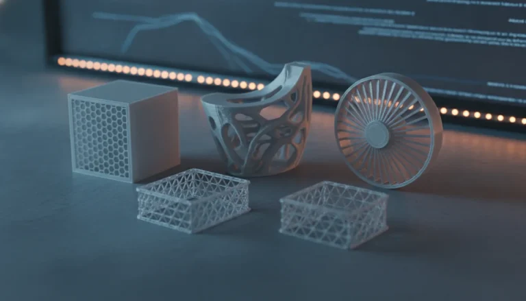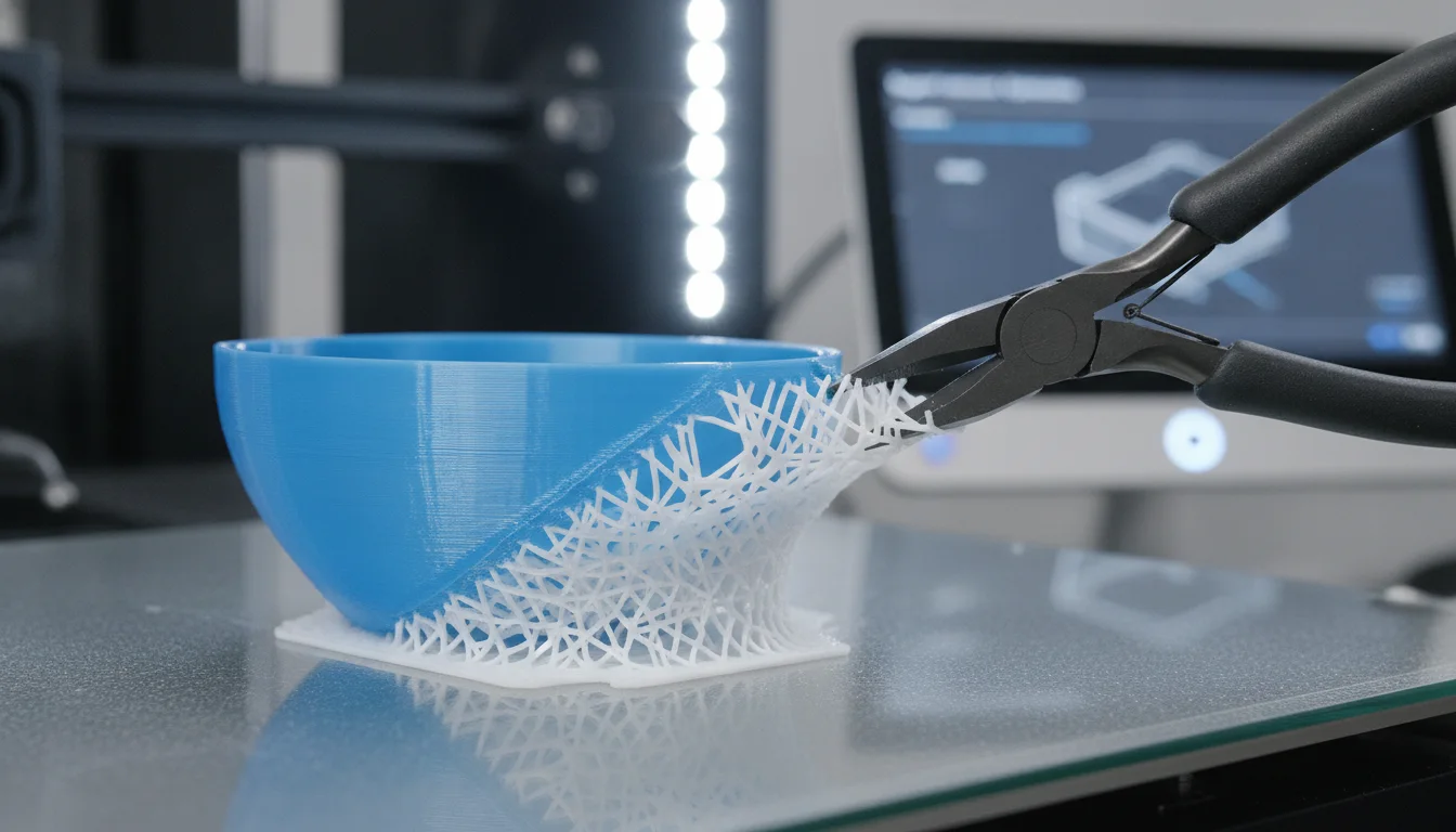
In the intricate world of FDM 3D printing, achieving pristine print quality often hinges on mastering the often-overlooked yet critically important element: the support interface. This specific part of your support structure acts as the crucial intermediary between the printed model and its necessary scaffolding. Its proper configuration is paramount, directly influencing both the surface finish of supported areas and the ease with which supports can be removed without damaging your final print. Delving into the nuances of these settings allows for a significant leap in print consistency and overall user experience.
Understanding the vital role of the support interface
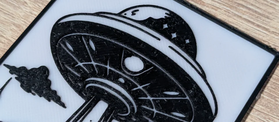
Every model we design and test gets uploaded as a free STL – browse the full profile on MakerWorld.
The support interface refers to the topmost layer or layers of the support structure that directly contact the underside of your 3D print. While the main body of the support provides structural integrity to overhangs and bridges, it’s the interface that dictates the quality of the surface it touches. A well-tuned support interface ensures that your print has sufficient adhesion to prevent sagging or deformation, yet remains just detached enough to allow for clean, non-destructive removal. Without a carefully considered interface, you might find yourself battling with either rough, scarred surfaces or supports that are stubbornly fused to your model.
Key slicer settings for fine-tuning your support interface
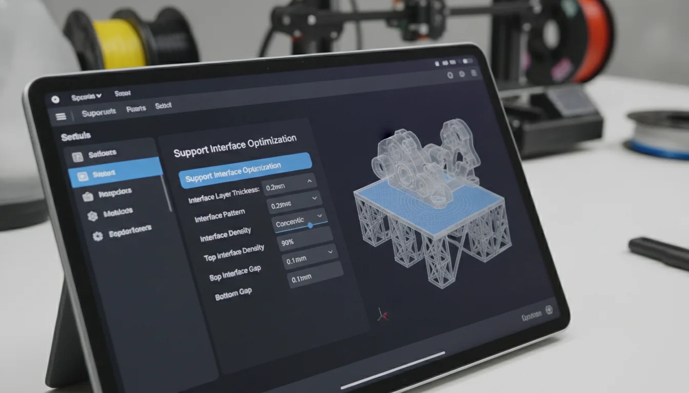
Modern slicer software offers a robust suite of controls to fine-tune the support interface. Understanding how each setting contributes to the final outcome is essential for achieving optimal results. Let’s explore the most impactful parameters:
Z distance: balancing adhesion and detachment
The Z distance, also known as the Z gap or vertical separation, is arguably the single most critical setting for the support interface. It defines the vertical space between the very top of your support structure and the bottom of the printed part. This microscopic gap is fundamental to both print quality and support detachment.
- A smaller Z distance (e.g., 0.1mm – 0.2mm): This brings the support interface very close to the printed part, resulting in more contact points and often a smoother surface finish on the supported areas. The closer proximity helps prevent significant sagging of the initial layers printed over the supports. However, the trade-off is that supports can become significantly harder to remove, sometimes fusing to the part and potentially causing damage or leaving noticeable scarring upon detachment. This might be considered when print quality on the supported surface is absolutely paramount and a bit more effort in post-processing is acceptable.
- A larger Z distance (e.g., 0.25mm – 0.35mm or more): Increasing the Z distance creates a larger gap, which dramatically eases support removal. With less material contact, supports tend to break away cleanly with minimal effort. The drawback, however, is that a larger gap can lead to poorer surface quality on the underside of your print. The initial layers bridging the gap might sag or droop more noticeably, resulting in a rougher, less aesthetically pleasing finish. This approach is often favored when ease of removal is a higher priority than a perfectly smooth supported surface, or for parts where the supported area is not visible.
Optimizing Z distance often involves iterative testing. Factors such as your nozzle diameter, layer height, and the specific filament material (some materials like PETG tend to stick more aggressively than PLA) will influence the ideal value. A common starting point is often one layer height or slightly less, but experimentation is key to finding the sweet spot for your specific printer and material combination.
Support interface pattern: shaping contact points
The support interface pattern dictates the infill geometry used for the top layers of the support structure. This pattern directly influences the number and distribution of contact points with your model, affecting both surface quality and detachment.
- Lines/Rectilinear: A common and often default pattern, consisting of parallel lines. It provides good support but can sometimes leave noticeable line patterns on the print. It’s generally easy to remove if Z distance is well-calibrated.
- Grid/Grille: Offers more robust support due to intersecting lines, potentially leading to a smoother surface. However, the increased contact points can make removal slightly more challenging than simple lines.
- Concentric: This pattern follows the contours of the model. It can offer excellent surface finish for rounded or organic shapes but might be harder to remove due to the continuous nature of the contact.
- Zigzag/Honeycomb: These patterns can provide a good balance between support and ease of removal, often breaking away cleanly due to their segmented nature.
Choosing a pattern involves considering the geometry of the supported area and your priority between surface finish and ease of removal. A denser pattern generally improves surface quality but increases removal difficulty, whereas a sparser pattern does the opposite.
Support interface layers/thickness: reinforcing the top
The number of support interface layers, or the interface thickness, determines how many solid layers form the top of your support structure. This setting adds robustness to the support interface itself.
- More interface layers (e.g., 2-4 layers): A thicker interface creates a more solid and stable base for the initial layers of your print. This can significantly improve the surface finish on the supported side, as there’s less chance of the print sagging into the gaps of a sparse support structure. The downside is that more material means more contact points and a stronger bond, potentially making the supports harder to remove.
- Fewer interface layers (e.g., 0-1 layer): A thinner or absent interface will lead to faster printing and easier removal, as there’s less material to break away. However, the trade-off is a higher likelihood of a rougher surface finish, as the print may sag more into the main support structure below. This option is generally considered for internal supports or areas where surface quality is not critical.
The optimal number of layers often depends on the complexity of the overhang and the desired surface quality. For critical surfaces, a thicker interface is usually preferred, accepting the increased effort in removal.
Support interface density: influencing contact points
The support interface density (sometimes referred to as interface infill percentage) dictates how densely packed the lines or patterns within the interface layers are. This directly controls the actual number of contact points between the support and the model.
- Higher density (e.g., 70-100%): A higher density means more material and more contact points. This provides excellent support, reducing sagging and leading to a much smoother surface finish on the supported area. The downside, much like with more interface layers, is that the increased contact makes supports significantly more difficult to detach, often requiring more force and careful post-processing.
- Lower density (e.g., 30-60%): A lower density means fewer contact points and less material, making supports much easier to remove. However, the reduced support can lead to a rougher surface finish with more visible sagging or imperfections on the underside of your print.
This setting offers a fine-grained control over the trade-off between surface quality and ease of removal. Experimenting with various densities can help you find a balance that suits your specific print requirements.
X/Y separation: horizontal clearance
While not strictly part of the interface layers, X/Y separation (or horizontal gap) is a crucial support setting that complements Z distance. It defines the horizontal distance between the vertical walls of the support structure and the vertical walls of your printed part.
- Smaller X/Y separation: Supports are closer to the model’s vertical walls, providing more robust support for angled overhangs. However, removal can be trickier, as supports might fuse or require more careful prying.
- Larger X/Y separation: Supports are further away, making them easier to remove. The trade-off is potentially less effective support for steep angles, leading to minor imperfections on vertical supported walls.
This setting, in conjunction with Z distance, creates a holistic strategy for support detachment and quality.
Material considerations for support interface settings
The choice of filament material significantly impacts how you should approach your support interface settings:
- PLA (Polylactic Acid): Generally the easiest material to work with for supports. It tends to bond less aggressively, making supports relatively easy to remove even with smaller Z distances.
- PETG (Polyethylene Terephthalate Glycol): Known for its strong layer adhesion, PETG can be notoriously sticky with supports. You might need a larger Z distance, a lower interface density, or even a larger X/Y separation to prevent supports from fusing to the print.
- ABS (Acrylonitrile Butadiene Styrene): Similar to PETG, ABS can also be challenging. It benefits from careful tuning of Z distance and potentially using a brim on supports to prevent warping.
- Flexible Filaments (e.g., TPU): These materials are often the most difficult for support removal due to their inherent flexibility and strong adhesion. A generous Z distance and sparse interface density are usually required, and sometimes even a completely different support strategy (like tree supports) is preferred.
Troubleshooting common support interface issues
Even with careful tuning, you might encounter issues. Here’s how to approach them:
- Supports stuck too hard / difficult removal:
- Increase Z distance incrementally.
- Decrease support interface density.
- Reduce the number of support interface layers.
- Experiment with a different interface pattern that has fewer contact points.
- For PETG/ABS, consider using a release agent or specific support materials if available.
- Poor surface finish on supported areas (roughness, sagging):
- Decrease Z distance incrementally.
- Increase support interface density.
- Increase the number of support interface layers.
- Try a different interface pattern (e.g., concentric for curved surfaces).
- Ensure proper cooling for the supported layers.
- Supports collapsing or failing to adhere to the build plate:
- This is less about the interface and more about the main support structure, but a very high Z distance can sometimes contribute if the first layer of the print struggles to bridge the gap.
- Check main support density, print speed, and build plate adhesion settings.
Advanced considerations for optimal results
The world’s first desktop full-color 3D & UV printer. Back the Kickstarter campaign with a refundable $50 deposit for VIP pricing.
While fine-tuning the basic interface settings is crucial, advanced techniques can further refine your results:
- Tree supports: These organic-looking supports often reduce the overall contact area and can be easier to remove, especially for complex geometries. Their interface settings are still important but might behave differently than standard supports.
- Soluble supports (e.g., PVA, HIPS): When using a dual-extruder printer, printing supports with a soluble material (like PVA for PLA/PETG or HIPS for ABS) completely eliminates the challenge of mechanical removal. This offers the cleanest possible surface finish with virtually effortless detachment, albeit at a higher material cost and requiring post-print dissolution. This is a “solution” that bypasses many of the interface dilemmas but introduces its own considerations regarding material compatibility and cost.
- Custom support blockers/enforcers: Many slicers allow you to manually define areas where supports should or shouldn’t be generated, or where specific support settings (including interface parameters) should apply. This offers granular control for critical areas.
Conclusion
The support interface is a small but mighty component in the quest for perfect 3D prints. There isn’t a single “best” setting; rather, optimal results emerge from a thoughtful understanding of the interplay between Z distance, interface patterns, layer counts, and density. Each choice represents a trade-off between the desire for pristine surface quality and the practicality of effortless support detachment. By systematically experimenting with these slicer settings, taking into account your chosen filament and the specific geometry of your model, you can confidently navigate the challenges of supported prints and consistently achieve professional-grade results.
Frequently asked questions
Will a smaller Z distance always give me a better surface finish?
Not always. While a smaller Z distance (e.g., 0.1mm) reduces sagging and often yields a smoother underside, it increases the risk of supports fusing to the print, which can cause scarring or damage during removal. The ideal Z distance balances surface quality with clean detachment, and the sweet spot depends on your material—PETG typically needs a larger gap than PLA to avoid sticking.
Can I use a support interface only on certain parts of my model?
Yes. Most modern slicers include custom support blockers and enforcers that let you apply specific support interface settings to selected areas. This gives you granular control—for example, using a denser interface on a visible overhang while using a sparser, easier-to-remove interface on an internal cavity where surface finish doesn’t matter.
Is it worth buying soluble supports (PVA/HIPS) to avoid interface tuning altogether?
Soluble supports like PVA (for PLA/PETG) or HIPS (for ABS) eliminate mechanical removal entirely and produce the cleanest possible surface finish, but they come with trade-offs. You need a dual-extruder printer, the filament is significantly more expensive, and the dissolution process adds time and post-processing steps (soaking in water or limonene). For most users, careful tuning of Z distance and interface density is more cost-effective.