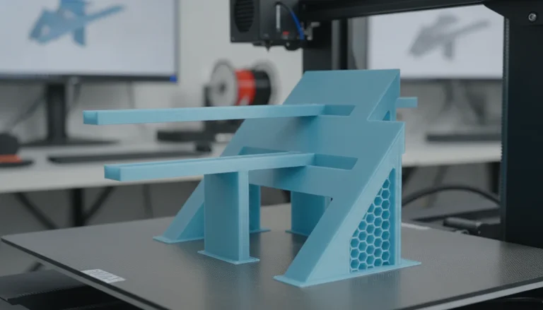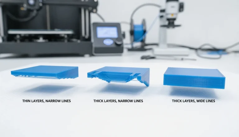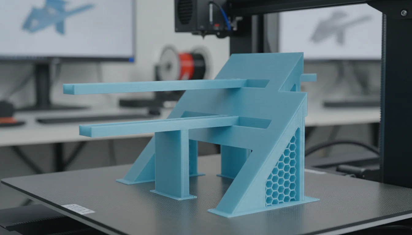
Achieving successful 3D prints, particularly with Fused Deposition Modeling (FDM) technology, often hinges on the quality and foresight embedded in the initial 3D model design. One of the most common challenges faced by enthusiasts and professionals alike is the necessity of support structures, which can increase material consumption, extend print times, and add significant post-processing work. The pursuit of support-free printing is not merely about convenience; it’s a strategic approach to enhance efficiency, reduce costs, and improve the aesthetic quality of finished parts.
This guide delves into the principles of engineering models specifically for support-free bridges and overhangs, focusing on intelligent design optimization. By understanding the inherent limitations and strengths of FDM, designers can craft geometries that defy gravity without external aids, making prints cleaner, faster, and more economical.
Understanding bridges and overhangs in FDM design
Before diving into optimization techniques, it’s crucial to define what constitutes a bridge and an overhang in the context of FDM design:
- Overhangs: These are features of a model that extend outwards, away from the layer below, without direct support from the build plate or underlying layers. The degree of an overhang is typically measured by its angle relative to the vertical. A 45-degree overhang is generally considered the maximum self-supporting angle for most FDM printers and materials.
- Bridges: These are horizontal spans that connect two raised points of a model, with no material directly beneath them. During printing, the printer extrudes filament across an open space, relying on the material’s ability to solidify and adhere to the anchor points before sagging excessively.
Both bridges and overhangs present unique challenges to printability. Without careful design, they can lead to sagging, delamination, or complete print failure. The goal is to incorporate design elements that allow the printer to successfully deposit material in these unsupported areas.
Core principles for support-free 3D model design
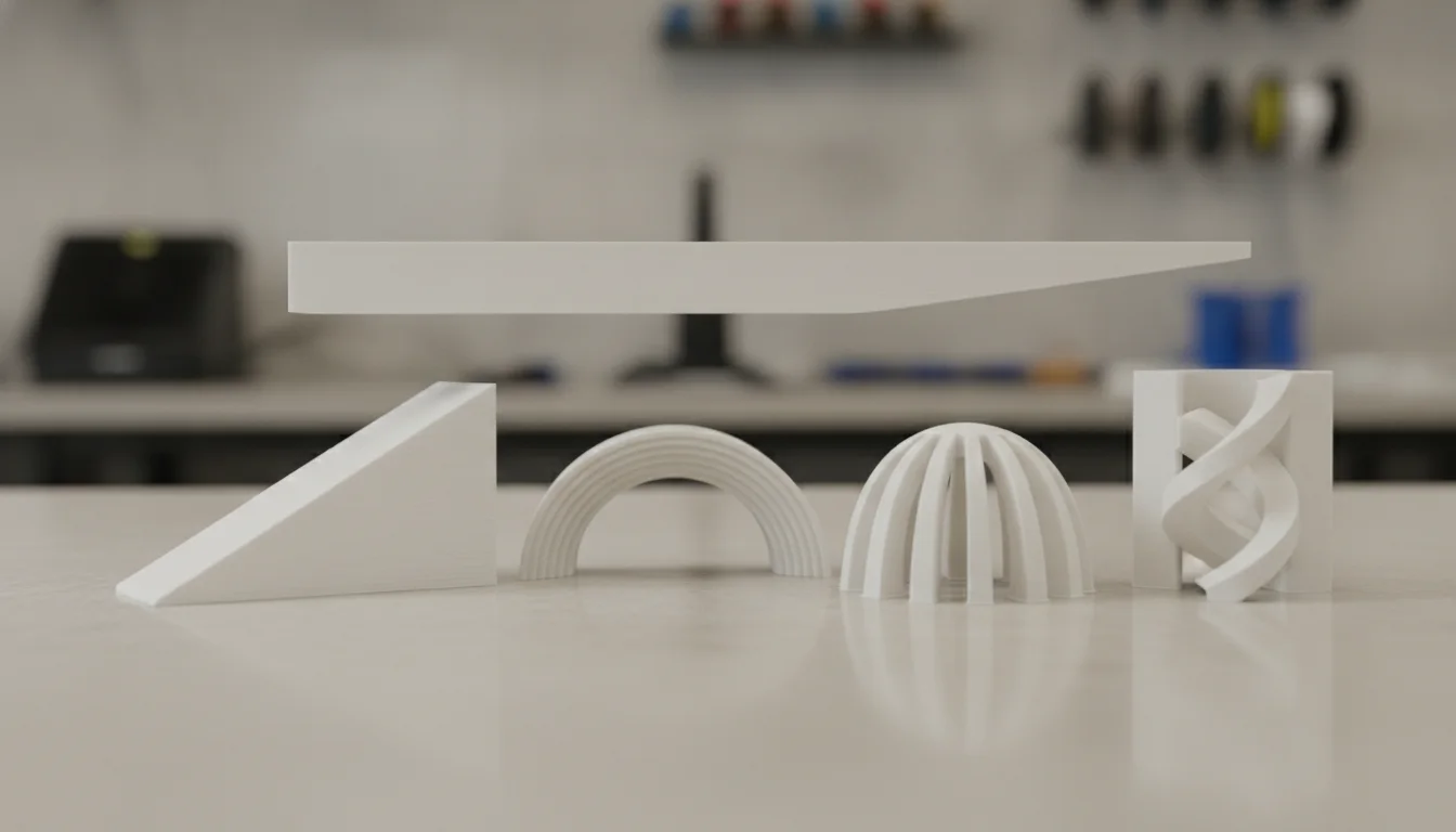
Effective 3D model design for support-free printing involves a blend of geometric foresight and an understanding of material science. Here are key principles:
The 45-degree rule and beyond
The golden rule for overhangs is often cited as the “45-degree rule.” This suggests that any surface angled at 45 degrees or less from the vertical (i.e., 45 degrees or more from the horizontal) can generally be printed without supports. The previous layer provides enough surface area for the new layer to adhere to and build upon. However, this is a guideline, not a hard limit. Some well-tuned printers with good cooling can manage steeper angles, sometimes up to 60-70 degrees, but pushing these limits requires careful calibration and material choice.
Optimizing bridge geometry
For bridges, the primary goal is to minimize the unsupported span and maximize the chances of successful filament deposition. Strategies include:
- Shortening spans: Redesigning parts to break up long bridges into shorter, more manageable segments.
- Optimized cross-sections: Using geometries that inherently support themselves. For example, a triangular cross-section for a bridge can be more robust than a rectangular one.
- “Teardrop” designs: For holes or circular features, shaping the underside as a teardrop or an inverted arch can significantly improve printability by ensuring that no part of the circle is truly horizontal and unsupported for long.
- Sacrificial bridging layers: In some cases, a thin, easily removable layer can be designed as part of the model to act as a temporary support for a critical bridge, which is then removed post-print. This is different from conventional supports as it’s integrated into the design for a specific purpose.
Incorporating chamfers and fillets
Sharp corners and abrupt transitions often exacerbate overhang issues. By replacing sharp edges with chamfers (angled cuts) or fillets (rounded edges), designers can create gradual transitions that are much easier for the printer to handle. A chamfer on the underside of an overhang effectively reduces the overhang angle, while a fillet provides a larger surface area for subsequent layers to bond to, improving layer adhesion and reducing the likelihood of warping.
Strategic part orientation
Sometimes, the best design optimization isn’t about changing the model’s geometry but its orientation on the build plate. Rotating a part can transform challenging overhangs into self-supporting angles or reduce the length of critical bridges. While this isn’t strictly part of the 3D model design itself, it’s a crucial consideration during the design phase, influencing how the model should be prepared for printing.
Leveraging CAD for 3D printing for design optimization
Modern CAD for 3D printing software offers powerful tools that can significantly aid in creating support-free designs. These tools range from basic geometric modeling to advanced analysis features that help predict printability issues before a single layer is printed.
Features for printability analysis
Many CAD packages include features specifically designed to help identify and rectify issues related to printability:
- Draft analysis: This tool allows designers to visualize surfaces that fall below a certain angle (e.g., 45 degrees from the vertical), highlighting areas that will likely require supports.
- Overhang detection: Similar to draft analysis, some software can specifically identify and color-code overhangs, giving a clear visual indication of problematic areas.
- Section analysis: Examining cross-sections of a model can reveal hidden complexities or potential weak points that might impact support-free printing.
- Simulation tools: While more advanced, some CAD software offers basic simulation capabilities that can predict how a part might behave during printing, including potential for sagging or warping.
Comparing design approaches and their implications
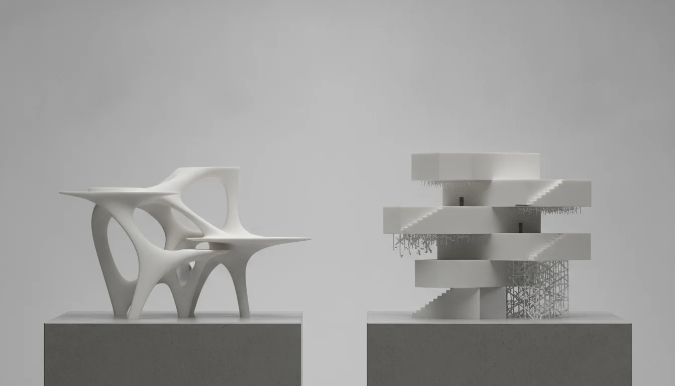
When approaching 3D model design for support-free FDM printing, designers often weigh different methodologies, each with its own “cost structure” in terms of time, skill, and potential for iteration. It’s not about comparing different software packages directly, but rather the investment in design methodology and the tools that facilitate it.
Manual iterative design versus feature-rich CAD utilization
One approach involves extensive manual iteration and physical prototyping. A designer might create a model, print it, identify support-requiring areas, modify the design, and repeat. This method, while seemingly “low cost” in terms of initial software investment (perhaps using free or basic CAD tools), can incur significant “costs” in:
- Time: Each iteration takes time for design, slicing, printing, and post-analysis. Failed prints are time sinks.
- Material waste: Failed prints mean wasted filament.
- Learning curve (trial and error): While valuable, learning solely through physical prototyping can be inefficient.
Conversely, investing in more advanced CAD for 3D printing software, which offers robust analysis and design optimization tools, represents a different cost structure. The initial “cost” might be a subscription fee or a software license. However, the “features” offered by such software can lead to substantial savings:
- Reduced iteration cycles: By identifying and correcting printability issues virtually, the number of physical prototypes can be drastically cut down.
- Minimized material waste: Fewer failed prints translate directly to less wasted filament.
- Faster time-to-print: Optimized designs require less preparation and are more likely to succeed on the first attempt.
- Enhanced design quality: Advanced tools can enable more complex, yet printable, geometries that would be difficult to achieve through trial and error.
The “cost structure” here isn’t just monetary; it includes the value of a designer’s time, the efficiency of the prototyping process, and the ultimate quality and reliability of the printed parts. A design approach that prioritizes upfront analysis and optimization, even if it requires an investment in software features, often yields long-term benefits in terms of project efficiency and material economy.
Conclusion
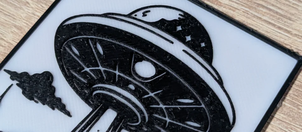
Every model we design and test gets uploaded as a free STL – browse the full profile on MakerWorld.
Mastering 3D model design for support-free FDM printing is a skill that significantly elevates the quality and efficiency of 3D printing workflows. By applying principles of intelligent geometry for bridges and overhangs, coupled with the analytical power of CAD for 3D printing, designers can transform challenging prints into straightforward successes. The choice of design methodology, whether relying on iterative physical prototyping or leveraging advanced software features for virtual design optimization, impacts the overall “cost” and efficiency of the entire printing process. Ultimately, informed design decisions lead to superior parts, reduced waste, and a more streamlined production pipeline, underscoring the critical role of thoughtful design in achieving true support-free printing mastery.
Frequently asked questions
Will a 45-degree chamfer on the underside of a hole always make it printable without supports?
No. The 45-degree rule is a guideline, not a guarantee. While a chamfer that results in a 45-degree angle from vertical is generally self-supporting on a well-tuned printer, factors like layer height, cooling, and material choice can shift this limit. Some printers with good cooling can handle steeper angles up to 60-70 degrees, but pushing beyond 45 requires careful calibration and testing with your specific setup.
Do teardrop-shaped holes print without supports in any orientation?
No, teardrop shapes are orientation-dependent. The teardrop design works by ensuring the top of the hole is an inverted arch rather than a flat horizontal span, which prevents a long unsupported bridge. However, if you rotate the part so the teardrop’s point faces downward, you can create a severe overhang that violates the 45-degree rule, so the part must be oriented with the rounded bottom of the teardrop facing the build plate.
Is it always cheaper to design for supports than to buy advanced CAD software for support-free design?
Not necessarily. While advanced CAD software has an upfront cost, the article highlights that manual iterative design with physical prototyping incurs hidden costs in time, material waste from failed prints, and slower iteration cycles. For frequent printing, the savings from fewer failed prints, reduced filament waste, and faster time-to-print can quickly offset the software investment, making it more economical in the long run.