For anyone deeply involved in the world of additive manufacturing, encountering a problematic 3D model is par for the course. One of the most vexing issues that can crop up, often leading to failed prints and wasted material, is the presence of non-manifold edges within an STL file. These seemingly innocuous geometric flaws can wreak havoc on your slicing software and ultimately compromise the structural integrity and aesthetic quality of your printed parts. Understanding what non-manifold edges are, why they occur, and most importantly, how to fix them, is a crucial skill for any 3D printing enthusiast or professional. This comprehensive guide will walk you through the process, ensuring your STL files are print-ready and your 3D printing endeavors are smooth sailing.
What exactly are non-manifold edges?

In the realm of 3D geometry, a "manifold" object is one that can exist in the real world – think of any solid, physical object. Mathematically, a manifold surface is one where every point on the surface has a neighborhood that resembles a flat disk. In simpler terms, if you were to zoom in on any point on a manifold object's surface, it would look like a flat plane. Conversely, a non-manifold edge is a geometric anomaly where this condition is violated.
Specifically, an edge is considered non-manifold if it is connected to more than two faces (polygons) or fewer than two faces. Imagine a single edge that forms part of three or more distinct surfaces – this is a classic non-manifold condition. Another common scenario is a "T-junction" where an edge terminates abruptly into the middle of another face, or two faces meeting at a single vertex without a shared edge, creating a "zero-thickness" wall. These situations break the fundamental rules of a watertight, solid model, making it impossible for slicing software to correctly interpret the object's interior and exterior.
Why non-manifold edges cause 3D printing errors
The implications of non-manifold geometry for 3D printing are significant and almost always detrimental. Slicing software, which translates your 3D model into layer-by-layer instructions for your printer, relies heavily on a perfectly enclosed, watertight mesh to determine what's "inside" and what's "outside." When non-manifold edges are present, this fundamental distinction becomes blurred, leading to a cascade of 3D printing errors:
- Slicing failures: The most immediate consequence. Slicers may fail to generate G-code, report errors, or produce an empty or incomplete print path.
- Missing layers or features: Parts of your model might simply not be printed, or internal structures like infill could be absent where they should be.
- Incorrect infill generation: The slicer might misinterpret volumes, leading to infill being generated in unintended areas or not at all, compromising part strength.
- Weak or fragile prints: Areas with non-manifold edges often result in walls that are not properly joined or are only partially printed, leading to structural weaknesses.
- Excessive print time or material usage: In some cases, the slicer might try to "fix" the issue by generating redundant geometry or print paths, increasing print time and material consumption unnecessarily.
- Printer crashes or unexpected behavior: While less common, severely corrupted STL files can sometimes lead to firmware errors or unexpected movements from the printer.
In essence, non-manifold edges are a primary cause of printability issues, transforming what should be a straightforward printing job into a frustrating troubleshooting exercise.
Common causes of non-manifold edges
Understanding the root causes can help prevent these issues from the outset:
- Poor CAD modeling practices: Overlapping geometry, surfaces that don't perfectly meet, or creating zero-thickness walls are frequent culprits.
- Boolean operations gone wrong: When combining or subtracting complex shapes, CAD software can sometimes generate messy edges if the source geometries aren't perfectly aligned.
- Import/export errors: Converting models between different file formats or software can sometimes introduce mesh corruption.
- Sculpting software issues: Organic modeling or sculpting tools, especially when working with dynamic meshes, can inadvertently create non-manifold geometry if not carefully managed.
- Low-quality scanned data: 3D scans often produce noisy, incomplete meshes that require significant cleanup, including manifold repair.
Identifying non-manifold edges: The first step to STL repair
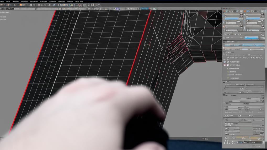
Before you can fix a problem, you need to know it exists. Most modern 3D modeling and slicing software offer tools to inspect your mesh for errors. Look for features like "analyze," "repair," "inspect," or "mesh analysis." These tools will often highlight problematic areas in red or another distinct color. While some slicers might give a warning, a dedicated mesh repair tool will provide a more detailed diagnosis.
Tools for STL repair: A comparative overview
Fortunately, several software solutions are available to help you tackle non-manifold edges and ensure proper STL repair. These tools vary in complexity, cost, and feature set, allowing users to choose based on their needs and expertise.
MeshMixer
Cost: Free.
Features: Developed by Autodesk, MeshMixer is a powerful, user-friendly tool specifically designed for working with mesh models. It excels at analyzing, repairing, and preparing models for 3D printing. Its "Inspector" tool is particularly adept at identifying and automatically fixing common mesh errors, including non-manifold edges, holes, and self-intersections. It offers both automated and manual repair options, making it a versatile choice for many users.
Blender
Cost: Free and open-source.
Features: Blender is a comprehensive 3D creation suite, encompassing modeling, sculpting, animation, and rendering. While its primary focus isn't just mesh repair, its robust modeling and editing tools, along with specific add-ons (like 3D Print Toolbox), make it highly capable of addressing non-manifold issues. It offers fine-grained control for manual repair, but its learning curve can be steeper for beginners solely focused on mesh fixing.
Netfabb
Cost: Paid (subscription-based, professional-grade).
Features: Also an Autodesk product, Netfabb is an industry-standard software for additive manufacturing. It offers advanced tools for STL repair, optimization, and preparation. Netfabb's repair capabilities are highly automated and extremely robust, making it suitable for professional environments dealing with complex and high-volume print jobs. Its cost reflects its professional feature set and extensive automation.
Professional CAD software (e.g., SolidWorks, Fusion 360, Onshape)
Cost: Varies (often paid subscriptions, some offer free personal/educational licenses like Fusion 360).
Features: While primarily used for designing solid models, many CAD programs have some capabilities for mesh analysis and repair, especially for models originating within the software. They often allow for direct manipulation of the solid model, which is the ideal way to prevent non-manifold edges from forming in the first place. For existing STLs, their mesh repair tools might be less intuitive or powerful than dedicated mesh editors, but they can sometimes convert a mesh back into a solid for repair. Fusion 360, for example, offers decent mesh tools.
Online STL repair services
Cost: Varies (some free for basic repair, others paid for advanced features or larger files).
Features: Websites like MakePrintable (now part of Materialise Cloud) or the built-in repair services of some 3D printing platforms can offer quick, automated repair. You upload your STL, and the service attempts to fix it. These are convenient for simple issues but may lack the control needed for complex problems.
For this tutorial, we will focus on MeshMixer due to its excellent balance of power, ease of use, and its free availability, making it an accessible choice for most users grappling with non-manifold edges.
Step-by-step tutorial: Fixing non-manifold edges with MeshMixer
This guide will walk you through using MeshMixer to identify and resolve common mesh issues, including non-manifold edges, ensuring your model is perfectly watertight for 3D printing.
Step 1: Download and install MeshMixer
If you don't already have it, download Autodesk MeshMixer from the official Autodesk website. It's free and available for Windows and macOS. Install it like any other software.
Step 2: Import your STL file
- Launch MeshMixer.
- Click 'Import' in the main menu or drag and drop your STL file directly into the MeshMixer window.
- Select 'Append' if you're adding it to an existing scene, or 'Replace' if it's the only model you're working on.
Step 3: Access the Inspector tool
With your model loaded:
- Navigate to the 'Analysis' tab on the left-hand toolbar.
- Click on 'Inspector'. This tool is your best friend for identifying 3D printing errors.
Step 4: Understand the Inspector's findings
Once you click 'Inspector', MeshMixer will analyze your model and highlight any detected errors with colored spheres or lines. The most common errors you'll see are:
- Blue spheres: Represent small holes.
- Magenta spheres: Indicate non-manifold edges or vertices. These are our primary concern.
- Red spheres: Often point to self-intersections or other complex mesh defects.
A small pop-up window will also appear, showing a summary of detected errors, such as "Non-Manifold Edges," "Open Boundaries," or "Self-Intersections."
Step 5: Automatic repair
MeshMixer's Inspector tool offers powerful automatic repair capabilities:
- In the Inspector window, click the 'Auto Repair All' button. MeshMixer will attempt to automatically fix all detected issues.
- For many common problems, especially small holes and straightforward non-manifold edges, this one click is often sufficient. The colored spheres should disappear.
- After auto-repair, re-run the Inspector (click 'Inspector' again) to confirm that all issues have been resolved. Sometimes, fixing one problem reveals another, or a particularly complex area might require a second pass.
Step 6: Manual repair for persistent non-manifold edges (if needed)
If 'Auto Repair All' doesn't fully resolve all magenta spheres (non-manifold edges), or if you want more control, you'll need to perform manual repairs. This often involves using other MeshMixer tools in conjunction with the Inspector.
- Identify the problematic area: Zoom in on the magenta spheres. They often appear where surfaces intersect incorrectly or where edges are shared by too many faces.
- Select and delete problematic faces/edges:
- Go to the 'Select' tool (S key).
- Use the brush to select the faces around the non-manifold edge. You might need to adjust the brush size and type (e.g., 'Sphere' or 'Lasso').
- Once selected, press 'Delete' (or 'X' key) to remove the corrupted geometry. This will likely create a large hole.
- Bridge or fill the hole:
- With the hole created, go back to the 'Analysis' tab and click 'Inspector' again. The large hole should now appear as a blue sphere.
- Click on the blue sphere representing the hole, and MeshMixer will suggest a fill. You can often choose between 'Flat Fill', 'Minimal Fill', or 'Smooth Fill' depending on the desired outcome. 'Minimal Fill' often works best for maintaining surface integrity.
- Alternatively, use the 'Bridge' tool under 'Edit' (E key) to connect two open edges across a gap, providing more control over the new geometry.
- Sculpt and refine: For very complex or organic shapes, you might need to use the 'Sculpt' tools (Shift+S) to smooth out the newly repaired area and blend it seamlessly with the rest of the model. Tools like 'Smooth' or 'Brush' can be helpful.
Repeat these steps until the Inspector reports no more non-manifold edges or other critical errors.
Step 7: Export the repaired STL file
Once your model is clean and free of errors:
- Go to 'File' > 'Export'.
- Choose 'STL Binary' as the format for efficiency.
- Give your file a new name (e.g., "model_repaired.stl") to avoid overwriting the original.
- Click 'Save'.
Your newly exported STL file should now be free of non-manifold edges and ready for your slicer, significantly reducing the chances of printability issues.
Best practices to avoid non-manifold edges from the outset

Prevention is always better than cure. Adopting good modeling habits can drastically reduce the occurrence of non-manifold edges:
- Use solid modeling principles: Design with solid objects rather than surfaces whenever possible. Ensure all bodies are closed and watertight.
- Check for intersections: Regularly use intersection analysis tools in your CAD software to identify and resolve overlapping geometry.
- Be mindful of Boolean operations: When performing unions, subtractions, or intersections, ensure the input geometries are clean and well-defined. Avoid operations that result in zero-thickness walls or coincident faces.
- Simplify complex geometry: Excessive detail or tiny features can sometimes lead to mesh errors during export or conversion. Simplify where appropriate.
- Regularly inspect your mesh: Make it a habit to use mesh analysis tools within your CAD or modeling software before exporting to STL.
- Export settings: When exporting to STL, choose appropriate resolution settings. Too low a resolution can sometimes simplify geometry to the point of creating gaps, while too high can create excessively large files without proportional benefit.
Conclusion
Conquering non-manifold edges is a vital skill in the arsenal of any 3D printing enthusiast. While they can be a source of frustration, understanding their nature and employing the right tools and techniques for STL repair can transform a problematic model into a perfect print. By following this MeshMixer tutorial and adopting best practices in your design workflow, you'll be well-equipped to tackle common 3D printing errors and ensure excellent printability issues are a thing of the past. Happy printing!