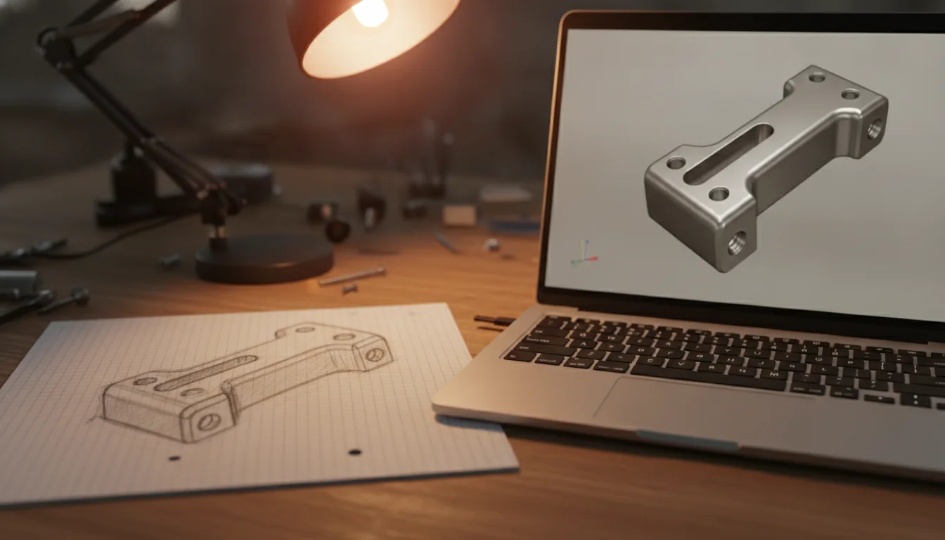
Somewhere between the napkin sketch and the finished print, a flat idea has to become a solid one. That jump trips up more beginners than any single CAD tool ever does, because the software isn’t hard to click through — the hard part is understanding how a line on paper, with no depth at all, turns into a wall with a thickness, a hole with a diameter, and a part that either fits its mating piece or doesn’t. This guide walks through that translation from concept to 3D model in the order it actually happens on a real project: sketch first, then a deliberate choice of software, then the sketch-to-solid step itself, then the printability checks that decide whether your first object comes off the plate looking like your drawing or like a warped approximation of it.
Start with the sketch, not the software
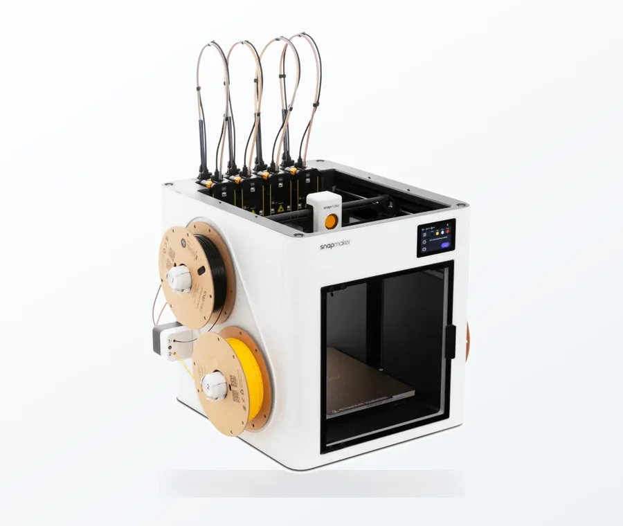
The consumer toolchanger 3D printer: the SnapSwap 4-toolhead system swaps heads in 5 seconds for true multi-color and multi-material printing, with smart calibration and auto filament loading.
- 4 toolheads · 5 s swap
- Up to 500 mm/s · 20,000 mm/s²
- 270 mm cube build volume
- Multi-color & multi-material
The instinct for most beginners is to open Fusion 360 or Tinkercad and start dragging shapes around until something looks right. That works for a phone stand, but it falls apart the moment your object needs to fit around something else — a specific screw, a shelf edge, another printed part. Before touching any modeling software, sketch the object on paper or graph paper with real numbers on it: overall length, width, height, and every dimension that has to match something in the physical world. If you’re designing a bracket for a 20 mm aluminum extrusion, that 20 mm needs to be on the sketch before you open CAD, not decided halfway through modeling because it “looked about right” on screen.
This is also where you decide what the part actually has to do, which shapes every choice downstream. A purely decorative object tolerates loose dimensions and rounded-off numbers. A functional part — a mount, a clip, a spacer — needs you to write down which surfaces are structural, which faces mate against something else, and which dimensions are load-bearing versus cosmetic. Engineers call this a design intent, and skipping it is why so many first CAD attempts produce a model that looks correct on screen but needs three redesigns once it meets a real screw or a real shelf.
A quick habit worth building here: sketch three views of anything that isn’t perfectly symmetric — front, top, and side — the same way technical drawings have done for over a century. You don’t need drafting-grade precision, just enough that width in the top view matches width in the front view. This three-view discipline is exactly what a 3D modeling package asks you to recreate digitally in its first sketch plane, so doing it on paper first means you’re not solving two problems — what the object looks like, and how to operate the software — at the same time.
Reading a flat sketch in three dimensions
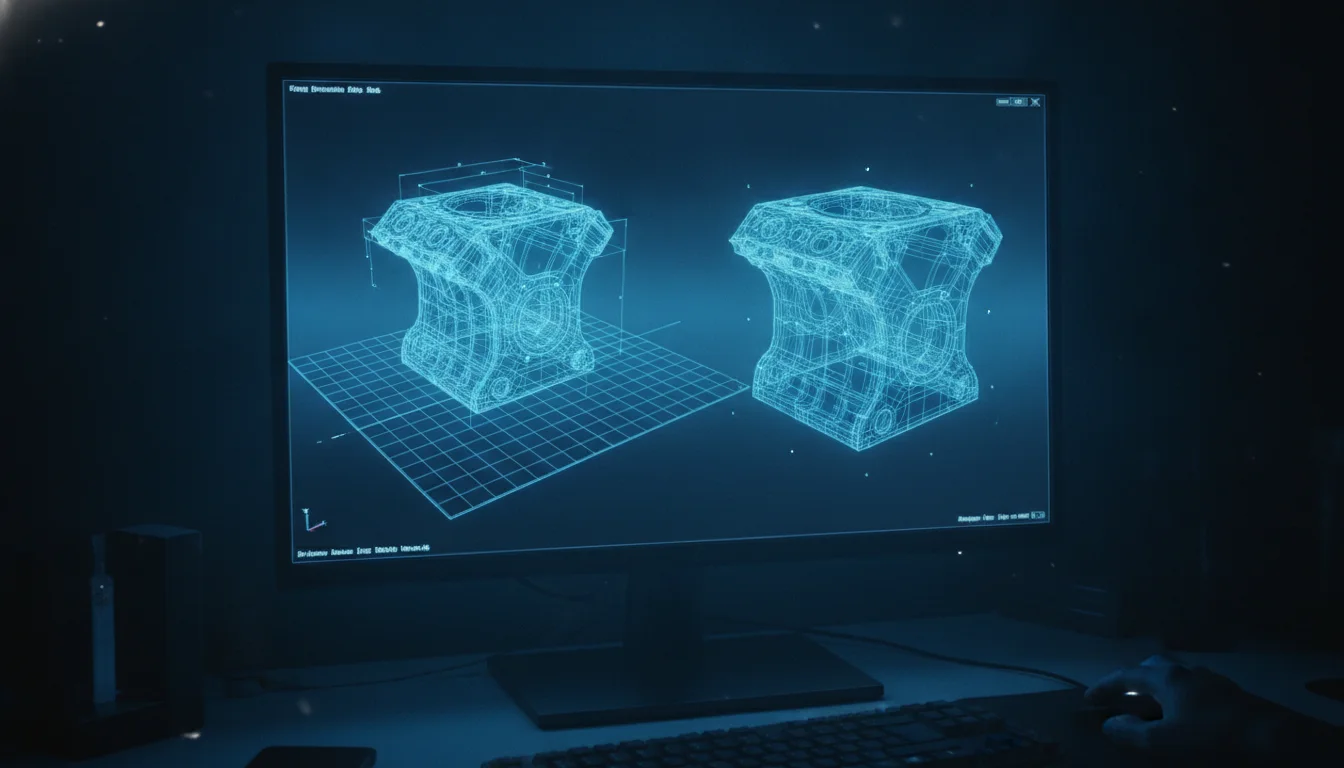
Every CAD package, whether it’s FreeCAD, Fusion 360, or Onshape, builds 3D geometry from a 2D sketch drawn on a flat reference plane, then adds the third dimension through an operation like extrude or revolve. Understanding this pipeline is the single biggest unlock for someone coming from 2D drawing or graphic design, because it means your paper sketch isn’t just inspiration — it’s close to a literal first step. The front view of your object becomes a sketch on the XZ plane, extruded along Y for its depth; the top view becomes a sketch on the XY plane, extruded along Z for its height. Pick whichever view carries the most detail as your starting sketch, since everything else gets added afterward as separate features.
Scale and units catch more beginners than any modeling command. CAD software defaults vary — Fusion 360 defaults to inches unless you set the design to millimeters at file creation, while FreeCAD’s default template is usually millimeters already. Set your unit system before you draw a single line, and confirm it again before you export, because a part modeled correctly in inches but exported and sliced as though it were millimeters comes out 25.4 times too small — a common enough mistake that it has its own name in maker forums: “the inch-to-mm print.”
If your original sketch was hand-drawn, most CAD tools let you import it as a reference image and trace over it — Fusion 360 calls this a canvas, FreeCAD handles it through an image workbench, and even Tinkercad accepts a traced SVG import. Scale the imported image against one known dimension from your sketch — say, that 20 mm extrusion width — before tracing anything else, so every other line you draw on top inherits the correct real-world scale automatically instead of being redrawn by eye and rounded off.
Choosing the right tool for the shape you’re building
Not every concept-to-3D-model workflow calls for the same software, and picking based on what your object actually needs saves hours over picking based on what tutorial you watched last. Parametric CAD — Fusion 360, FreeCAD, Onshape — is built for anything with exact dimensions, screw holes, flat mating faces, or measurements pulled from a datasheet; every dimension stays editable after the fact, so if your bracket needs to move from a 20 mm extrusion to a 25 mm one next week, you change one number and the whole model updates. This is the right category for brackets, enclosures, jigs, and spare parts.
Primitive-based tools like Tinkercad skip the sketch-and-constrain workflow in favor of combining boxes, cylinders, and other basic shapes with boolean union and subtract operations, driven by numeric input boxes instead of geometric constraints. It’s a genuinely good starting point for simple functional objects — a pen holder, a cable clip, a simple standoff — and for teaching the underlying logic of solid modeling without the vocabulary overhead of constraints and sketch planes. It gets frustrating fast, though, once you need a hole positioned exactly between two other features or a shape that isn’t built from rectangles and circles.
Sculpting and mesh tools — Blender, Nomad Sculpt, ZBrush — throw out exact dimensions almost entirely in favor of pushing and pulling a digital clay surface, which is the right call for organic shapes: figurines, cosplay props, terrain, anything where “looks right” matters more than “measures exactly 42.5 mm.” Trying to model a precise mechanical bracket by sculpting is painful and imprecise; trying to sculpt a dragon head in parametric CAD is even worse. Match the tool to whether your object is defined by measurements or by silhouette, and the rest of the workflow gets noticeably easier.
Turning a flat profile into a solid
With a scaled, traced, or hand-drawn sketch sitting on a plane, the actual 2D-to-3D moment happens through one of three operations, and picking the right one matters as much as drawing the sketch correctly. Extrude pushes a closed 2D profile in a straight line to create depth — a rectangle becomes a box, an L-shaped profile becomes an angle bracket. It’s the default choice for anything with flat, parallel faces, which covers the large majority of functional printed parts.
Revolve spins a profile 360 degrees (or any partial angle) around an axis, which is how anything round in cross-section gets modeled — knobs, spacers, bottle-shaped containers, a doorknob or a wheel hub. A single half-profile, revolved around its centerline, produces a perfectly symmetric round part from a fraction of the sketch geometry a full extrude-and-boolean approach would need. If your object has a cross-section that stays constant while rotating around a center point, revolve is almost always faster and more accurate than trying to build the same shape from cylinders and boolean cuts.
Loft and sweep handle the cases extrude and revolve can’t: a shape that changes profile along its length, like a handle that’s oval at one end and round at the other, or a curved tube that follows a path instead of a straight line. These are more advanced operations and worth learning after you’re comfortable with extrude and revolve, since forcing a lofted shape where a simple extrude would do adds modeling complexity without adding accuracy. As a rule of thumb: reach for extrude first, revolve for anything round in cross-section, and loft or sweep only when the shape genuinely changes as it travels through space.
Where the model meets the machine
The consumer toolchanger 3D printer: the SnapSwap 4-toolhead system swaps heads in 5 seconds for true multi-color and multi-material printing, with smart calibration and auto filament loading.
A geometrically correct model can still fail on the print bed, because a screen has no wall thickness minimums, no overhang limits, and no gravity. Before exporting, check minimum wall thickness against your printing process: for FDM with a standard 0.4 mm nozzle, anything under about 0.8 mm risks being skipped by the slicer entirely, and a wall meant to carry any real load should sit closer to 1.2 mm, matching three perimeter passes. Resin printers tolerate thinner unsupported walls, often down to 0.4–0.5 mm, but thin resin walls are fragile through cleaning and curing, so print-safe isn’t the same as durable on either process.
Overhangs are the second place a clean digital model meets a physical limit. FDM printers handle angles down to roughly 45 degrees from vertical without support; steeper than that and the layer below can’t hold up the layer being deposited on top of it, producing sagging or a rough, drooping surface. If your sketch-to-solid workflow produced a feature that juts out past that angle — a shelf, an arm, an unsupported boss — either add a chamfered lead-in in CAD or plan on supports in the slicer, but decide which one deliberately instead of finding out after a failed print.
Tolerances decide whether two printed parts actually fit together the way your original sketch intended. A hole meant to let an M3 screw pass through freely wants roughly 3.4 mm diameter, not the screw’s nominal 3 mm; two printed parts meant to press-fit together typically need 0.15–0.3 mm of clearance per side to account for how FDM printers slightly over-extrude the first wall against open air. None of these numbers are guesswork you can skip — they’re the difference between a part that snaps together on the first print and one that needs three iterations of “add 0.1 mm, reprint, check again.” Before committing to a full-size print, it’s worth printing a small test feature — just the hole, just the snap-fit tab — to confirm your printer’s real-world tolerance before spending the material and time on the complete object.
Frequently asked questions
My sketch has a dimension that doesn’t match what I see on screen after importing it as a reference image. What went wrong?
The most likely cause is that you didn’t scale the imported image against a known real-world dimension before tracing. As the article notes, you should scale the image using one confirmed measurement from your paper sketch — such as a 20 mm extrusion width — so that every line you trace inherits the correct scale automatically. If you trace before scaling, your lines will be at the wrong size and you’ll have to manually adjust each one.
Should I set my CAD software to inches or millimeters for a 3D printing project?
Set it to millimeters before you draw a single line. The article warns that a part modeled in inches but exported and sliced as though it were millimeters comes out 25.4 times too small, a common beginner mistake. Most slicers and 3D printer firmware handle millimeters natively, so starting in that unit system avoids that error entirely.
What is the minimum wall thickness I should use for a functional FDM part?
For FDM with a standard 0.4 mm nozzle, anything under about 0.8 mm risks being skipped by the slicer entirely. A wall meant to carry any real load should sit closer to 1.2 mm, matching three perimeter passes. Resin printers tolerate thinner unsupported walls down to 0.4–0.5 mm, but those are fragile through cleaning and curing.