In the evolving landscape of 3D printing, the choice of infill pattern often dictates a print's final mechanical properties, weight, and material consumption. While traditional patterns like rectilinear or honeycomb have long been workhorses, the gyroid infill has emerged as a sophisticated alternative, captivating advanced users with its unique characteristics. This guide delves into the intricacies of gyroid infill, exploring its underlying principles, advantages, and considerations for optimizing complex 3D prints.
Understanding the gyroid infill

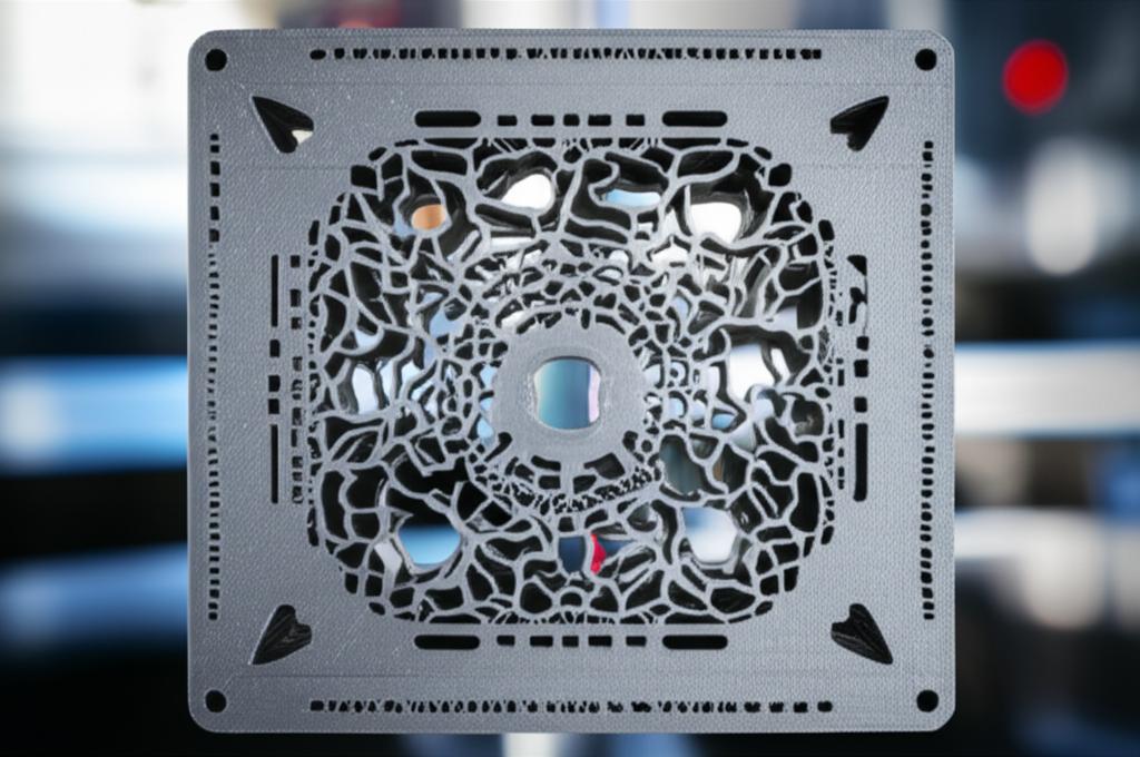
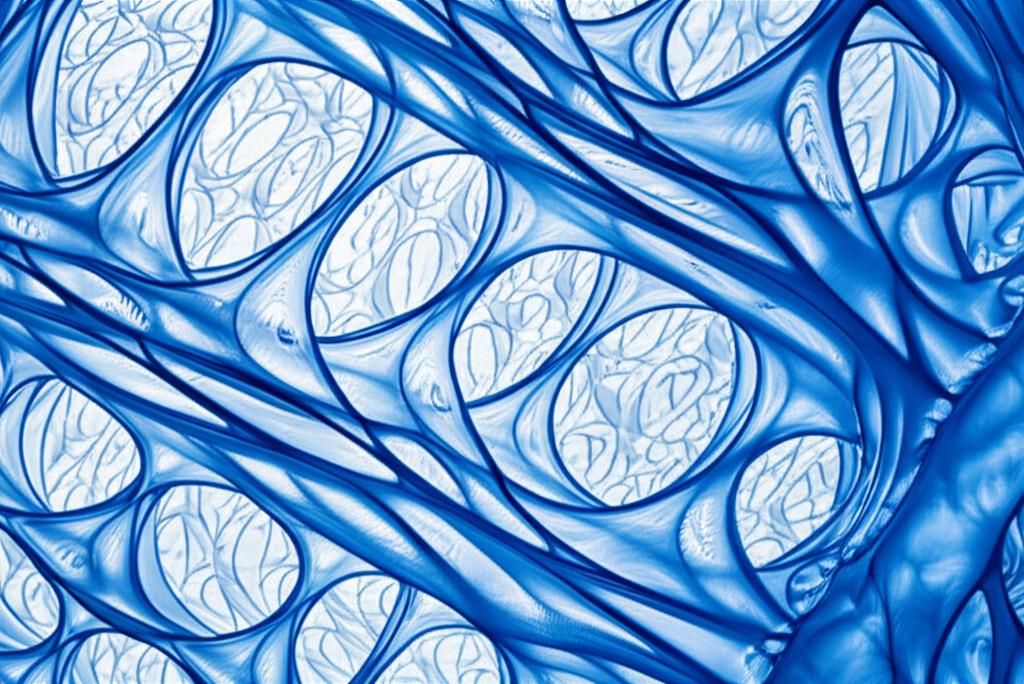
At its core, the gyroid is a triply periodic minimal surface (TPMS), a complex mathematical structure characterized by its non-self-intersecting, infinitely connected, and zero-mean curvature properties. In simpler terms, it's a beautifully intricate, wave-like structure that fills the interior of a 3D print. Unlike linear or grid-based patterns, the gyroid's continuous, curvilinear paths create a cellular structure that offers distinct benefits.
The science behind its structure
The gyroid's design is derived from a mathematical equation that generates a surface minimizing its area for a given volume, much like a soap film. This results in a structure that is both lightweight and incredibly robust. Its interconnected, open-cell network allows for a uniform distribution of stress across all axes, a property crucial for high-performance applications.
Key advantages of gyroid infill
The adoption of gyroid infill is driven by several compelling advantages that address common challenges in 3D printing, particularly for functional and engineering-grade parts.
Isotropic strength and structural integrity
One of the most significant benefits of gyroid infill is its ability to provide near-isotropic strength. Traditional infill patterns, such as rectilinear or grid, often exhibit anisotropic properties, meaning their strength varies significantly depending on the direction of applied force. A rectilinear infill, for instance, is typically strong along the infill lines but weaker perpendicular to them.
- Uniform Stress Distribution: The gyroid's continuous, curving paths distribute stress more evenly throughout the printed part, regardless of the direction of the load. This makes parts more resilient to forces from multiple angles.
- Reduced Delamination: Its interconnected nature can contribute to better layer adhesion, potentially reducing the risk of delamination compared to patterns with more abrupt changes in direction or disconnected segments.
Material efficiency and weight reduction
For applications where weight is a critical factor, or where material conservation is paramount, gyroid infill presents a strong case. Its unique geometry allows for significant material savings while maintaining impressive structural integrity.
- Optimized Material Placement: The TPMS structure inherently optimizes material placement, providing support where it's most needed without excessive bulk. This can lead to lighter parts that still meet strength requirements.
- Cost Implications: While print time can sometimes be slightly longer due to complex toolpaths, the reduction in material usage can offer a compelling trade-off, potentially lowering overall material costs for a given part's performance profile.
Improved heat dissipation
The open, interconnected cellular structure of gyroid infill also offers advantages in thermal management. For parts that generate heat or need to dissipate it efficiently, this can be a crucial factor.
- Enhanced Airflow: The continuous channels within the gyroid allow for better airflow and convection, facilitating heat transfer away from critical areas.
- Applications: This property can be particularly beneficial for enclosures for electronics, heatsinks, or parts operating in elevated temperature environments.
Support for complex geometries and flexible prints
Gyroid infill's continuous, non-intersecting structure makes it surprisingly versatile for various print types.
- Flexible Materials: When printing with flexible filaments like TPU, the gyroid's structure can enhance the part's flexibility and rebound properties, allowing for intricate designs that bend and compress uniformly.
- Overhangs and Bridging: While complex, the gyroid's self-supporting nature can sometimes reduce the need for extensive internal supports, especially for internal overhangs within the infill itself, though external overhangs still require standard support structures.
Comparing gyroid to other advanced infill patterns
To fully appreciate the gyroid's position, it's helpful to consider its characteristics alongside other popular infill patterns.
Gyroid versus cubic and honeycomb
Cubic and honeycomb patterns are also often chosen for their strength, but they differ significantly from gyroid in their structural anisotropy and material distribution.
- Cubic: Offers good strength in multiple directions but is not truly isotropic. Its intersecting lines can lead to stress concentrations at junctions. Material usage is often higher than gyroid for comparable strength in certain load cases.
- Honeycomb: Known for its high strength-to-weight ratio, particularly in the plane of the hexagons. However, it can be weaker perpendicular to this plane and may not offer the same isotropic performance as gyroid. It can also be more difficult to print cleanly due to numerous short movements.
- Gyroid: Excels in true isotropic strength and often achieves this with less material than cubic or honeycomb for many applications. Its smooth, continuous paths can also lead to more consistent print quality.
Print time and slicing considerations
The complexity of the gyroid pattern can influence print time and requires robust slicing software.
- Slicing Complexity: Generating the intricate toolpaths for gyroid infill can be more computationally intensive for slicers compared to simpler patterns.
- Print Time: While the continuous nature of the gyroid paths can sometimes reduce print time by minimizing retractions and abrupt direction changes, the overall path length can be longer than for simpler patterns at higher infill densities. Users may find that balancing infill density with print speed is key.
Advanced infill settings and optimization
Maximizing the benefits of gyroid infill involves a careful adjustment of various slicing parameters.
Infill density
This is arguably the most critical setting. A higher infill density translates to more material and greater strength, but also increased print time and material consumption. For gyroid, even lower densities (e.g., 10-20%) can provide substantial strength due to its efficient structure. Experimentation is key to finding the optimal balance for specific part requirements.
Perimeters (wall count)
The number of perimeters plays a significant role in a part's overall strength, often more so than infill density, especially for impact resistance. Combining a robust wall count (e.g., 3-5 perimeters) with a lower-density gyroid infill can yield a strong, lightweight part.
Top and bottom layers
Adequate top and bottom layers are essential to ensure a smooth finish and to fully encapsulate the infill. Too few layers can result in "pillowing" or visible infill patterns on the surface. For gyroid, 3-5 top/bottom layers are often sufficient, depending on layer height and nozzle diameter.
Infill line width and overlap
- Infill Line Width: Increasing the infill line width (e.g., to 120% of nozzle diameter) can improve adhesion between infill lines and reduce print time, though it might affect the visual quality of the internal structure if exposed.
- Infill Overlap: This setting determines how much the infill lines overlap with the perimeters. A slight overlap (e.g., 10-20%) can improve the bond between the infill and walls, contributing to overall part strength.
When to consider gyroid infill
While gyroid infill offers numerous advantages, it may not be the optimal choice for every single print. Its strengths shine brightest in specific scenarios:
- Functional Prototypes and End-Use Parts: Where isotropic strength and durability are paramount, such as brackets, gears, or structural components.
- Lightweighting Applications: When reducing mass without compromising strength is critical, like in robotics, drones, or automotive components.
- Flexible Parts: For achieving consistent flexibility and rebound in designs made with TPU or other elastomeric filaments.
- Parts Requiring Good Heat Dissipation: For enclosures or components that benefit from internal airflow.
- Aesthetic Applications: When an exposed internal structure (e.g., in transparent prints) is desired, the gyroid's organic look can be visually appealing.
Conclusion

The gyroid infill stands out as a sophisticated and highly effective pattern in the arsenal of 3D printing techniques. Its foundation in triply periodic minimal surfaces grants it exceptional isotropic strength, impressive material efficiency, and advantageous thermal properties. While requiring a bit more computational effort from slicers and potentially nuanced parameter tuning, the benefits it offers for functional, lightweight, and complex 3D prints are substantial. By understanding its unique characteristics and optimizing advanced infill settings, users can unlock the full potential of gyroid infill, pushing the boundaries of what's achievable in additive manufacturing and allowing for informed decisions regarding part performance and material utilization.
