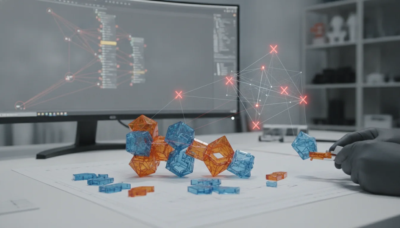
Parametric modeling has revolutionized the world of 3D design, offering unparalleled flexibility and efficiency. By defining relationships and parameters, designers can create intelligent models that adapt to changes, accelerating design iterations and reducing rework. However, this power comes with its own set of challenges. Without a clear understanding of its underlying principles and potential pitfalls, what begins as a dynamic, adaptable model can quickly devolve into a fragile, error-prone structure. This guide delves into the common parametric errors that plague even experienced designers, exploring their root causes and, more importantly, outlining robust strategies for error prevention and ensuring model stability.
What are parametric errors?
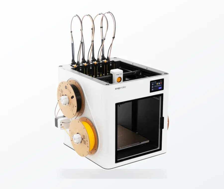
The consumer toolchanger 3D printer: the SnapSwap 4-toolhead system swaps heads in 5 seconds for true multi-color and multi-material printing, with smart calibration and auto filament loading.
- 4 toolheads · 5 s swap
- Up to 500 mm/s · 20,000 mm/s²
- 270 mm cube build volume
- Multi-color & multi-material
At its core, parametric modeling relies on dependencies: features are built upon other features, dimensions drive geometry, and equations link various aspects of the design. A parametric error occurs when one of these underlying dependencies breaks, becomes ambiguous, or leads to an undesirable outcome. These errors can manifest in various ways, from subtle warnings that hint at future problems to outright model failures that render a design unusable. Understanding these errors is the first step towards effective dependency management and creating truly robust 3D models.
Common categories of parametric errors
- Dependency errors: These are arguably the most common and frustrating. They arise when a feature loses its reference to a parent element, or when a circular relationship is inadvertently created.
- Broken references: Occur when a referenced sketch, face, edge, or plane is deleted or modified in a way that invalidates the child feature.
- Circular dependencies: A more complex scenario where Feature A depends on Feature B, which in turn depends on Feature A, creating an unsolvable loop.
- Feature reordering issues: Changing the order of features in the design tree can break dependencies if a child feature suddenly precedes its parent.
- Geometric instability: These errors relate to the underlying geometry itself, often resulting from conflicting constraints or ambiguous definitions.
- Over-constrained sketches: Adding too many dimensions or constraints to a sketch, making it mathematically impossible to solve.
- Under-constrained sketches: Not providing enough information, leading to unpredictable geometry when other features change.
- Degenerate geometry: Creating features that result in zero-thickness faces, tiny slivers, or self-intersecting geometry that the CAD kernel struggles to process.
- Tolerance issues: Accumulated precision errors, especially in complex models or when importing geometry, leading to gaps or overlaps.
- Propagation errors: These are errors that don’t necessarily break the model immediately but cause unintended consequences further down the design tree. A seemingly minor change in an early feature can ripple through the entire model, leading to unexpected deformations or failures in later features. This highlights the importance of anticipating design changes from the outset.
The root causes of parametric pitfalls
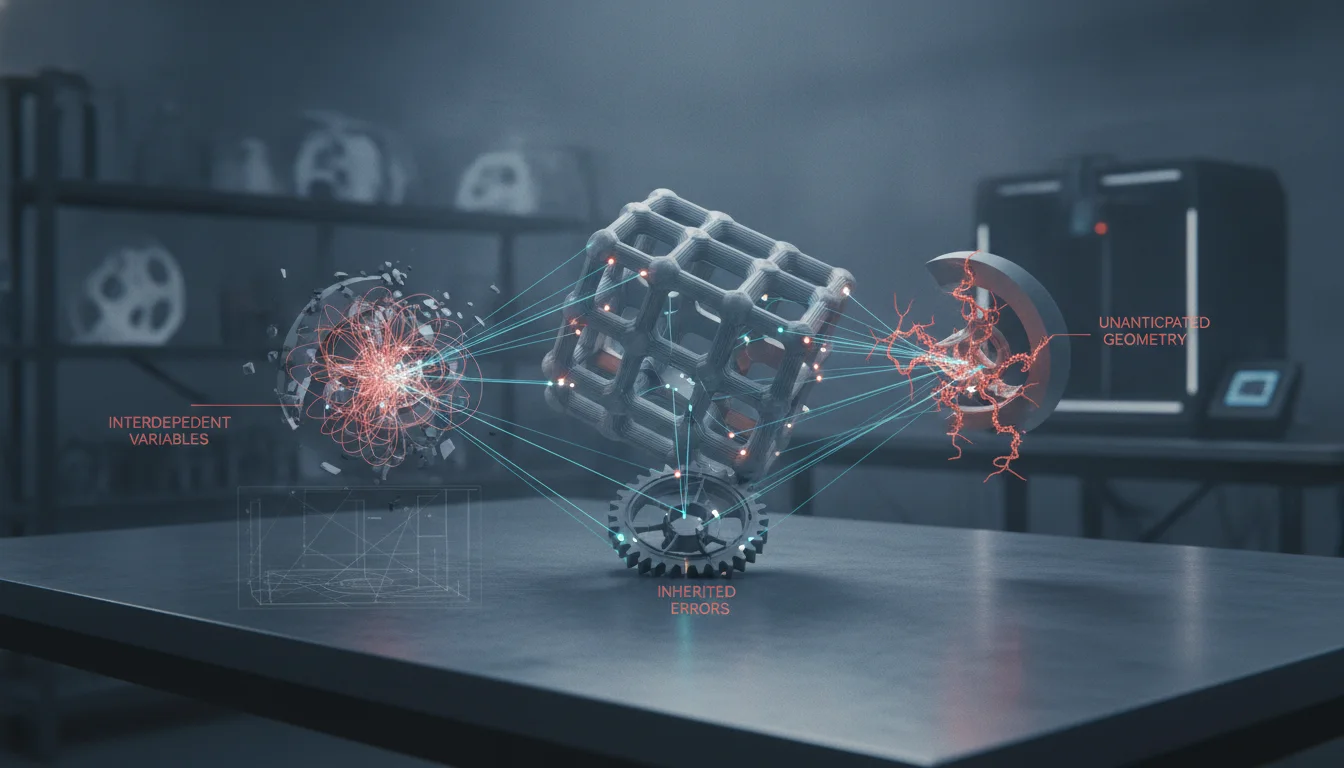
Identifying the symptoms is one thing; understanding the underlying causes is another. Many parametric errors stem from fundamental issues in design methodology and a lack of foresight regarding how a model might evolve.
- Poor design intent: Failing to plan how a model will be modified in the future. If a designer doesn’t consider which dimensions will drive changes and which will remain fixed, the model becomes brittle.
- Lack of modularity: Building a complex model as a single, monolithic structure rather than breaking it down into logical, independent components. This makes dependency management incredibly difficult.
- Over-reliance on automatic constraints: While helpful, automatic constraints can sometimes create unintended dependencies or over-constrain sketches without the designer’s explicit knowledge.
- Inconsistent naming conventions: Unclear or generic names for features, sketches, and parameters make it challenging to understand the model’s logic and troubleshoot when issues arise.
- Ignoring warning messages: CAD software often provides warnings before a full error occurs. Overlooking these can lead to larger problems later.
- Direct manipulation over parametric control: Manually moving or resizing geometry instead of modifying the underlying parameters or constraints breaks the parametric link and introduces instability.
Strategies for error prevention and robust modeling
Preventing parametric errors requires a proactive approach, integrating best practices throughout the design process. The goal is to build robust 3D models that are resilient to change and easy to modify.
Embrace strong design intent and planning
The foundation of a stable parametric model is a clear design intent. Before even touching the CAD software, consider:
- What are the critical dimensions? Identify which dimensions will drive the design and which are secondary.
- How will the model be modified? Anticipate future design changes and build flexibility into the model’s structure.
- Which features are primary, and which are secondary? Establish a logical hierarchy of features.
- Use reference geometry wisely: Base sketches and features on stable reference planes, axes, or origins rather than transient faces or edges that might disappear or change.
Master dependency management
Dependency management is key to preventing broken models. Think of dependencies as a family tree – every child needs a parent, and you don’t want any orphans.
- Build from simple to complex: Start with the most fundamental features and gradually add complexity. This ensures a stable base.
- Minimize external references: While powerful, referencing geometry from other parts or assemblies can introduce fragility. Use them judiciously and ensure the referenced files are stable.
- Modular design: Break down complex designs into smaller, manageable sub-components. This isolates dependencies and makes troubleshooting easier. For example, design a hole pattern as a separate feature or even a separate part if it’s reused.
- Feature ordering: Pay close attention to the order of features in your design tree. Ensure parent features are created before their children. Regularly review and reorder features for clarity and stability.
Ensure model stability and resilience
Beyond dependencies, several techniques contribute directly to model stability.
- Fully define sketches: Always aim for fully constrained sketches. This removes ambiguity and prevents unexpected shifts in geometry when other parts of the model change. Use dimensions and geometric relations (coincident, parallel, perpendicular, tangent, etc.) to achieve this.
- Use robust features: Opt for features that are inherently more stable. For example, a solid body extrusion is generally more robust than a complex surface patch if the design intent allows.
- Avoid degenerate geometry: Design with sufficient wall thicknesses, radii, and clearances to prevent the creation of zero-thickness geometry or impossible intersections.
- Parameterize effectively: Use equations and global variables to link related dimensions, ensuring consistency and making global changes easier. However, avoid overly complex or circular equations.
- Regularly rebuild and check: Most CAD software has a “rebuild” function. Use it frequently to catch potential issues early. Also, utilize built-in diagnostic tools to check for errors, gaps, or self-intersections.
Documentation and version control
These practices, while not directly related to geometry, are crucial for long-term error prevention and collaborative work.
- Clear naming conventions: Give meaningful names to features, sketches, planes, and parameters. “Extrude1” tells you nothing; “Main_Body_Extrusion” is far more helpful.
- Add comments: Use the commenting features within your CAD software to explain design intent, complex relationships, or potential areas of concern.
- Version control: Implement a system for saving different iterations of your model. This allows you to revert to a stable state if a significant error is introduced, making troubleshooting less daunting. Many CAD systems integrate with PDM/PLM solutions for this purpose.
Troubleshooting and recovery strategies
Even with the best practices, parametric errors can still occur. Knowing how to troubleshoot effectively is a critical skill for creating robust 3D models.
- Interpret error messages: Don’t just click “OK.” Read and understand the error messages. They often point directly to the problematic feature or dependency.
- Rollback the feature tree: Most CAD software allows you to roll back the design tree to an earlier state. This can help isolate when and where the error was introduced.
- Suppress features: Temporarily suppress problematic features to see if the rest of the model rebuilds correctly. This helps pinpoint the source of the issue.
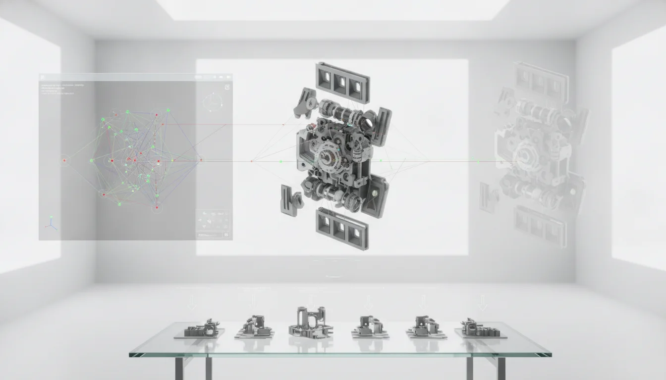
- Check parent-child relationships: Use the dependency viewer or similar tools in your CAD software to visualize the relationships between features. Look for broken or circular links.
- Simplify and isolate: If a complex feature is failing, try to simplify its inputs or recreate it in isolation to understand the underlying problem.
- Utilize diagnostic tools: Leverage built-in tools for geometry checks, interference detection, and sketch diagnostics.
Mastering parametric modeling is an ongoing journey that demands a blend of technical skill, foresight, and systematic problem-solving. By understanding the common parametric errors and diligently applying strategies for error prevention, dependency management, and ensuring model stability, designers can move beyond merely creating geometry. They can instead craft truly robust 3D models that stand the test of iterative design, adapting gracefully to change and serving as reliable foundations for innovation. The effort invested in building well-structured, stable parametric models pays dividends in reduced rework, faster design cycles, and ultimately, more successful product development.
Frequently asked questions
Can I fix a broken reference without starting over?
Yes, in most CAD software you can repair a broken reference by editing the affected feature and re-selecting the missing sketch, face, edge, or plane. Use the rollback feature to suppress the broken child feature, then edit its definition to point to a stable parent—such as a reference plane or origin—rather than a transient face that might change again. If the original parent geometry was deleted entirely, you may need to recreate it before reattaching the child.
How do I avoid circular dependencies when using global variables or equations?
Circular dependencies occur when two features reference each other in a closed loop, such as Feature A’s dimension equaling Feature B’s dimension and vice versa. To avoid this, always define a single source of truth for any parameter—use one global variable or equation as the driver, and make all other references read-only from that source. Never set up an equation where the output of one feature feeds back into its own input.
Why does my model still break even though all sketches are fully defined?
Fully defined sketches prevent ambiguous geometry within a single sketch, but they do not protect against broken dependencies between features. A common cause is referencing a transient face or edge from an earlier feature—if that face changes shape or is deleted, the dependent feature loses its anchor. Always base sketches and features on stable reference geometry like origin planes, axes, or fixed sketches rather than on faces generated by other features.